Handheld Tester Emulator Test Suite Worksheet
3
PAGE 103
[P] [F] A. Using the equipment user interface, verify that the passive equipment timers (TP1 through
TP5) are configurable within the range specified in E84 (1 to 999) and make note of the
default settings.
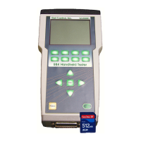
Use the HHT’s Tester Configuration (option 7 of Main Test Menu) to enter the passive
equipment timers into the HHT:
TP1 _______seconds
TP2 _______seconds
TP3 _______seconds
TP4 _______seconds
TP5 _______seconds
Notes:
Handheld Tester Emulator Test Suite Worksheet
3
PAGE 104
[P] [F] B. Verify for hard wired implementation the voltage provided by the unit under test (UUT) is
within the range specified in E84 under Full Load [100mA] and No Load [<2mA]. Both
measurements must be within the published range to pass.
UUT supplies voltage on Pin 23 of the E84 Interface.
1. Voltage at Full Load is in the range of 18VDC to 30VDC
2. Voltage at No Load is in the range of 18VDC to 30VDC
Also note voltage measured on Pin 22. This voltage should also fall within the published
range. A voltage measurement on Pin 22 that is less than 18 VDC implies an improperly
wired E84 interface.
Notes: