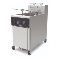
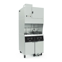
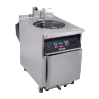
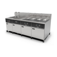
GBF-Series Fryers
Installation
7
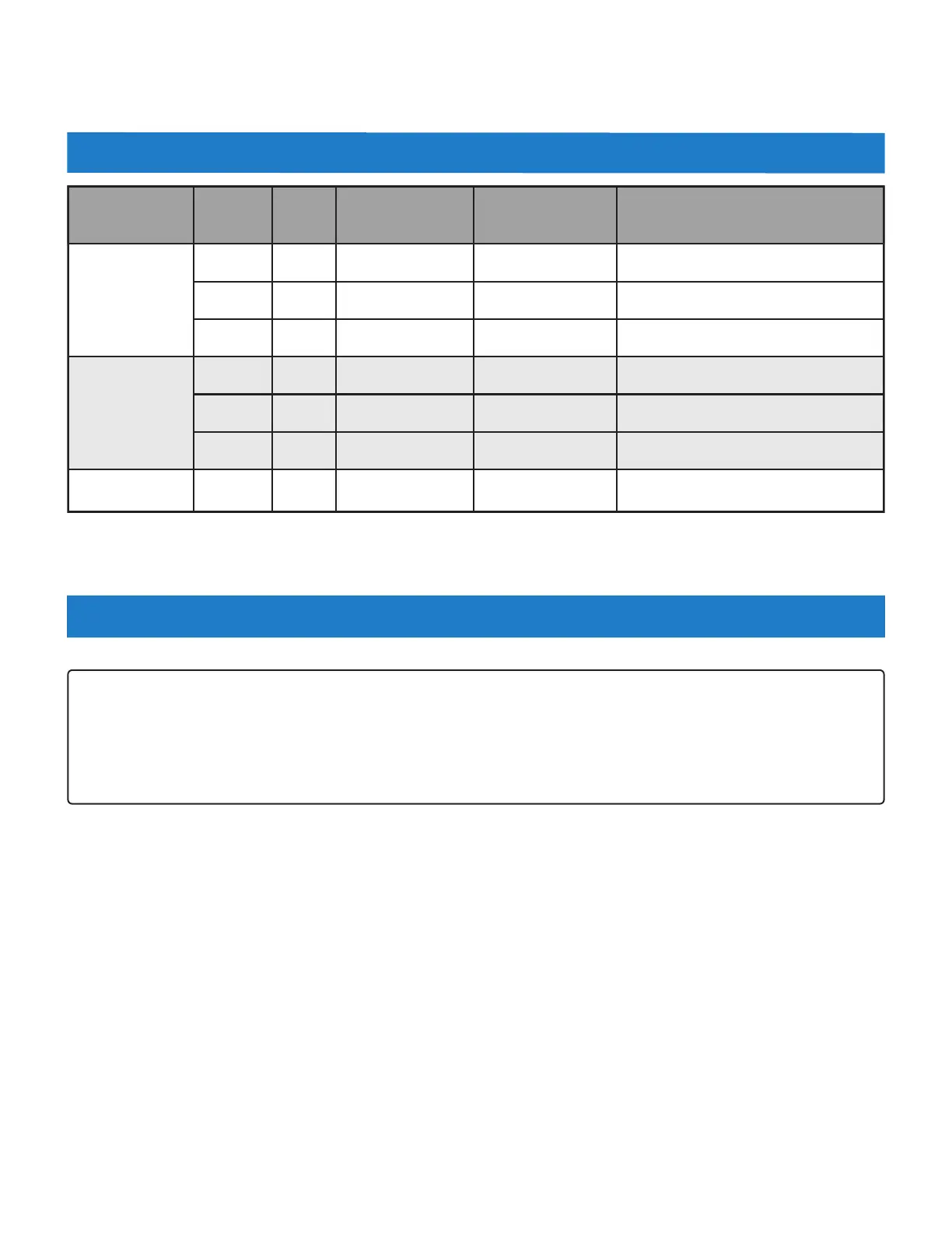
2.04 Electrical Specifications (per fryer unit)
Voltage
Phase Hz
Watts
Amps Circuit Breaker Required
208
1 60 10,000 50 60
3 60 10,000 28 35
3 60 18,000 51 60
240
1 60 10,000 43 50
3 60 10,000 24 30
3 60 18,000 44 50
380 ‐ 415 3 50 15,000 ‐18,600 26 ‐ 28 35
2.05 Electrical Connections
1. As needed, install appropriate circuit breaker(s) in main electrical panel. See Section 2.04.1.
2. Optional: Giles recommends that a service disconnect switch be installed between the main panel and the
appliance, such that all power may be easily removed from the unit when necessary.
3. See Section 2.05.1. Route 1‐1/4” flexible conduit from panel (or disconnect switch) to the appliance and attach
it to the rear of the Service Entrance Box with appropriate fittings. Allow enough conduit length so that
appliance may be easily moved for cleaning and servicing.
4. See Figure 2.05.1. Open cabinet door and remove Service Box Cover.
5. Connect ground wire between the copper ground lug and a proper earth ground.
6. Pull appropriately sized wires from the panel (or disconnect switch) through to the service entrance box.
7. See Figure 2.05.1. Connect power supply wires to the distribution block located inside the service box and
reinstall cover.
8. For banked system installation, each unit in the battery requires a separate power supply to be connected in
like manner.
NOTE:
All electrical installation labor & materials (breakers, conduit, wire, etc.) shall be supplied by the customer.
Electrical installation must be performed by a licensed electrician, or qualified service technician, as per local
building codes.
Installation must comply with all code requirements. Giles shall not be responsible for code compliance with
regard to installation and use of this appliance.
 Loading...