Red (24-40 V)
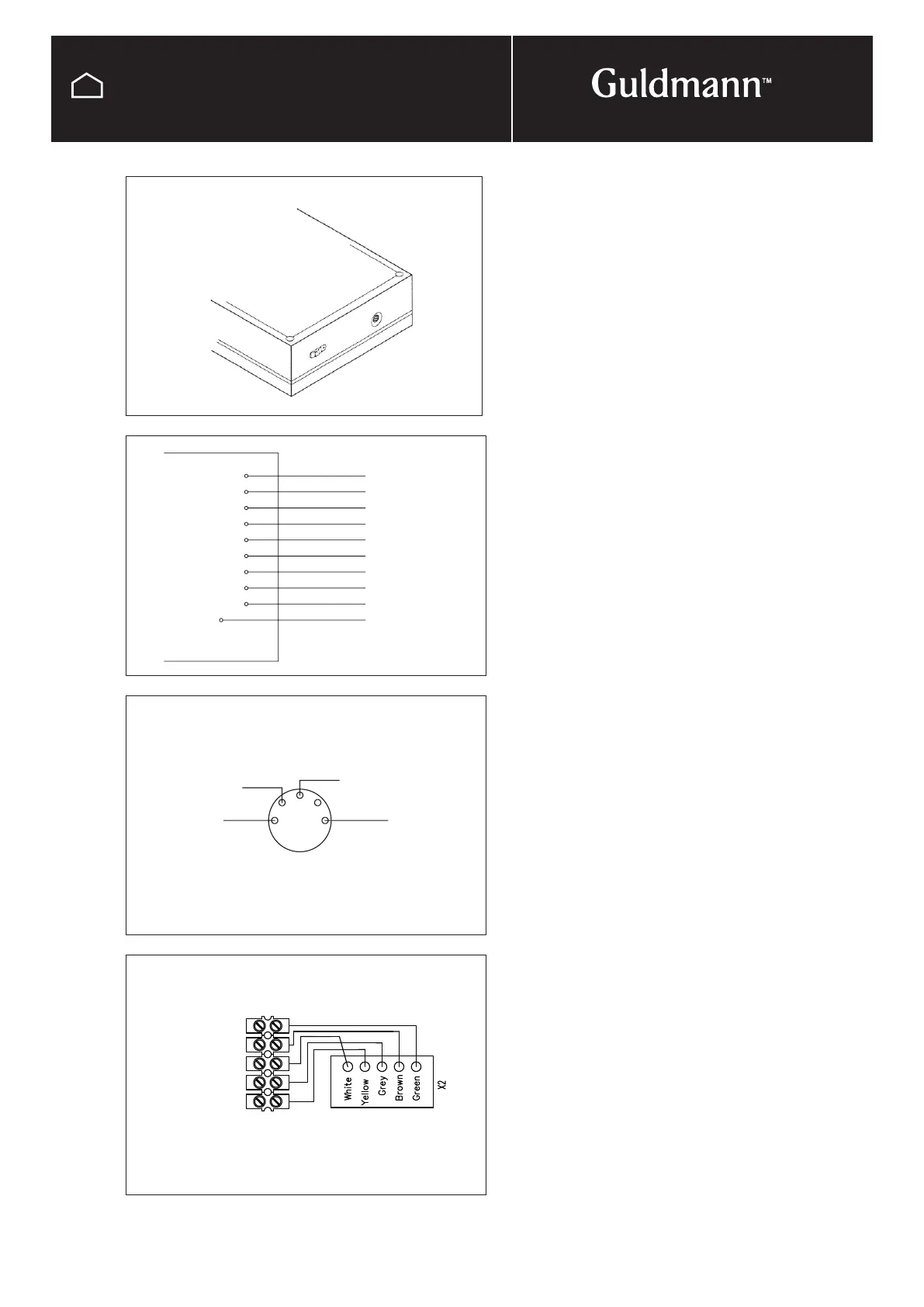
White
Gray 4
Brown 3
Yellow 2
Green 1
Blue 6
Orange 5
Black 8
Purple 7
V+
GND
FR
FH
KR
KH
NR
NH
5R
5H
Channel #
Red
Orange
Blue
White
2
4 5
1 3
Red
Blue
White
Not in use
Orange
Screw terminal Print connection
© Guldmann GB/US-09/2016 • #550376_3
94
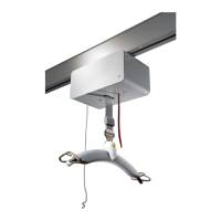
SERVICE AND REPAIR
IR remote control
IR-PCB for Combi-lock
Do the following on the IR-receivers:
Remove the 4 screws and the cover to get access to the
wiring.
Key no. 5: Mount the orange wire on NH (standard)
Key no. 6: Mount the orange wire on NR
Key no. 7: Mount the orange wire on 5H
Key no. 8: Mount the orange wire on 5R
Key no. 9 and 10 implies that only this IR-receiver is set to
channel 2 (Ch. 2).
Key no. 9: Mount the orange wire on 5H
Key no. 10: Mount the orange wire on 5R
Mount the cover on the IR-receiver with the 4 screws.
The IR-receiver can be mounted with a 5-pole plug which
fits the product’s input for the remote control.
If the IR-receiver does not have this plug, see wiring dia-
gram.
The IR-receiver is mounted with a piece of double sided
tape which makes it easy to install the IR-receiver as
appropriate as possible.
IR-receiver
Wiring for
IR-receiver