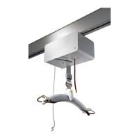
IR PCB
Brown
Pink
Grey
Green
Yellow
White
Supply
- +
2 1
Motor
Out
4 3
#1 Control
- Le Puri +
9 8 7 6 5
#2 Control
- Le Puri +
14 13 12 11 10
LED
- +
16 15
#1 SW
- IN +
19 18 17
#2 SW
- IN +
22 21 20
#3 SW
- IN +
25 24 23
#4 SW
- IN +
28 27 26
ON DIP
1 2 3 4 5 6 7 8 9 10
IR PCB
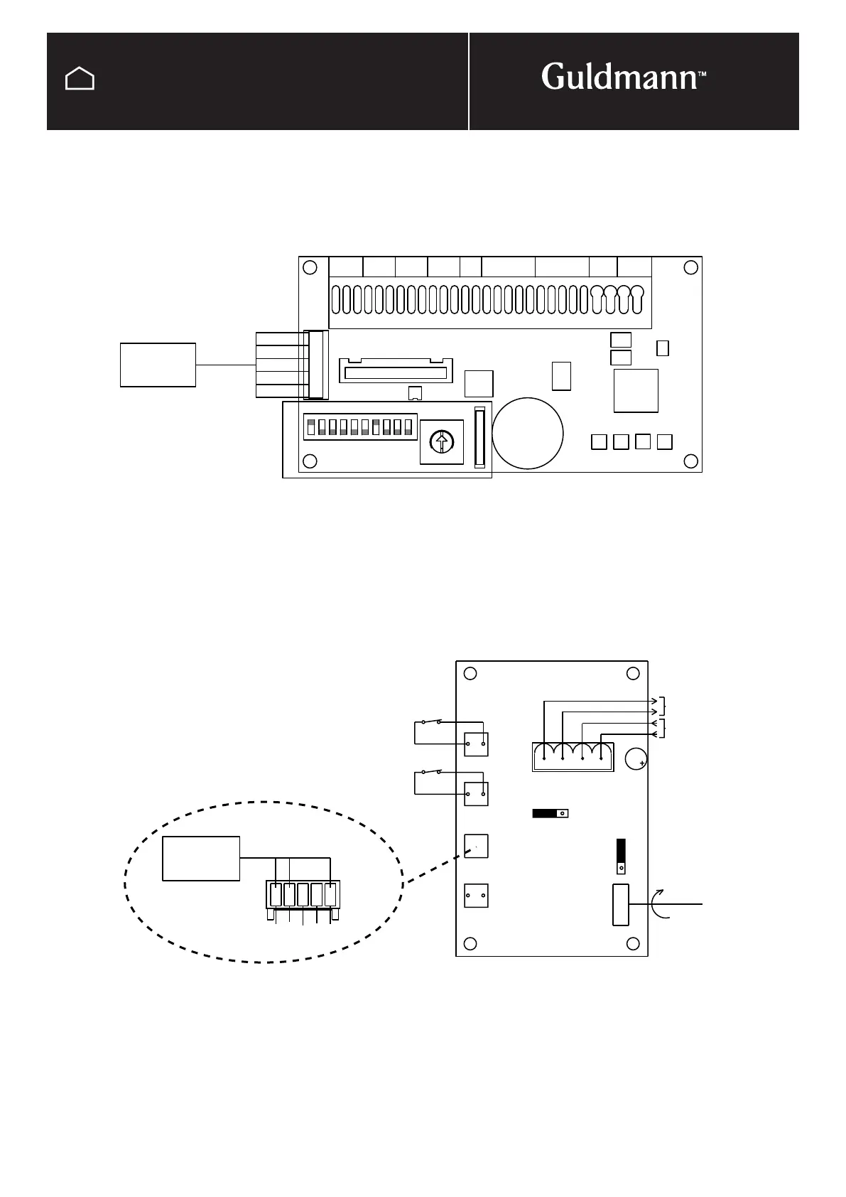
5 pol plug
Female Molex
Yellow
White
Black
24V DC
X2
LS1
1
2
X1
2
1
X3
1
4
24V AC
1
LS2
2
X4
X5
GND
GND
Brown
Black
Blue
Green
Blue
Yellow
Orange
Red
Max.
Min.
10 SEC.
Timer
Astable
SW1
OFF
LOCK
ON
BIST.
ASS.
Eg.: Bistable
combi lock
End stop 1
End stop 2
SW2
1
2
1
2
Motor
P010A
© Guldmann GB/US-09/2016 • #550376_3
93
SERVICE AND REPAIR
IR remote control
Switch track, Transverse drive motor
The IR-receiver is connected to the PCB for Switch track or
Transverse drive motor, by ”IR-receiver cable”
Turntable
The IR-receiver is connected to the PCB on the Turntable,
by ”IR-receiver cable”.