DIGITAL I/O
115
Digital I/O Terminal Configuration
Background
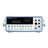
The digital I/O terminal outputs the result of Compare
measurements to control external devices. By providing
separate VCC power for the terminal, the outputs can also be
used as a power source for TTL and CMOS circuits.
Pin
assignment
Connector type: DB-9
female
CC output, 5V. Serves as the power source for
the external device/logic.
Pin2
NC (No Connection).
Pin3
Digital (chassis) Ground.
Pin4
External Trigger Input. Accepts external trigger
signals. For using external signals, see page 110
(Scanner) or page 72 (Configuration).
Pin5-9
Pins 5-9 use open-collector outputs and thus
require a pull-up resistor for each pin. The
output resistor must have a minimum rating of
500Ω. All the outputs are active low.
Pins 5-9
output

 Loading...