ES0609 rev D 4/09
33
dXF FI l e IM p o r t e r
This feature can quickly build a CNC G-code program from a DXF le, a drawing le format exportable from
many desktop CAD applications. Compatible DXF les are made up of arcs, lines, circles, vertices, and/or
points. Refer to your CAD application’s documentation for details on how to export a DXF le. When import-
ing a DXF le, you dene its features one by one as tool paths; G-code is generated for each tool path that
can then be placed in any new or existing program. DXF Importer for lathes is used to create ID and OD part
proles, for other features (threads, etc.), use IPS.
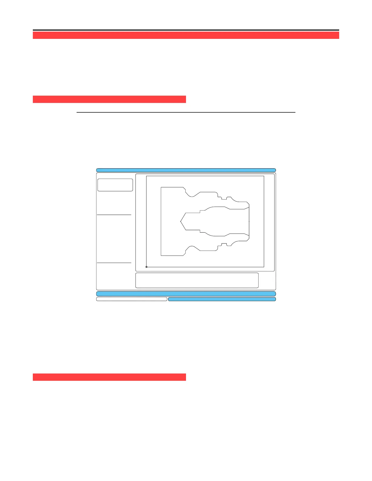
IM p o r t I n g t h e dXF FI l e
Note: Tools should be set up in IPS before starting this process.
1. Press LIST PROG, select the tab for the device (USB, Hard Drive, or Floppy) containing the DXF le and
press Write/Enter. Use the cursor arrows to highlight the DXF le and press Write/Enter to select it.
2. Press F2 and select “memory”. The control will recognize the DXF le and import it into the editor.
Exit (F1)
Zoom ON/OFF (F4)
Prev Chain pt (LEFT)
Next Chain pt (RIGHT)
Select Point (UP/DOWN)
Cancel Action (CANCEL)
Select Group (PG UP/DN)
Chng Line Width (ALTER)
Delete Group (DELETE)
Undo Group (UNDO)
X 0.0000
Z 0.0000
Type: START
Group: 0
Chain: 0
EXTRA KEY COMMANDS
Enter Origin Point: Use one of the following and press the WRITE key:
X: 0.0000 1) Jog toXandZposition on part. (Use jog axis keys)
Z: 0.0000 2) Use up and down arrows to select point.
3) EnterXandZcoordinates.
INPUT:
CURRENT GROUPS
TEST.DXF
EDIT: EDIT
The DXF importer feature provides on-screen help in the lower right corner of the display. The keys needed
are dened beside the steps. Additional keys are identied in the left hand column.
DXF Importer creates programs using simple input given in the following steps:
1. Set the part origin point
2. Chain a tool-path
3. Set the tool-path
4. Repeat steps 2 and 3 for remaining features
Se t t h e or I g I n po I n t
Use one of three methods:
Point Selection - Use the up and down arrow keys to select a point.•
Jogging - Jog to the X and Z position on a part (use jog axis keys).•
Enter Coordinates - Type in X coordinate and press WRITE/ENTER, then type in Z coordinate and press •
WRITE/ENTER.
 Loading...