ES0666 rev D 09/09
4
to o l Se t u p
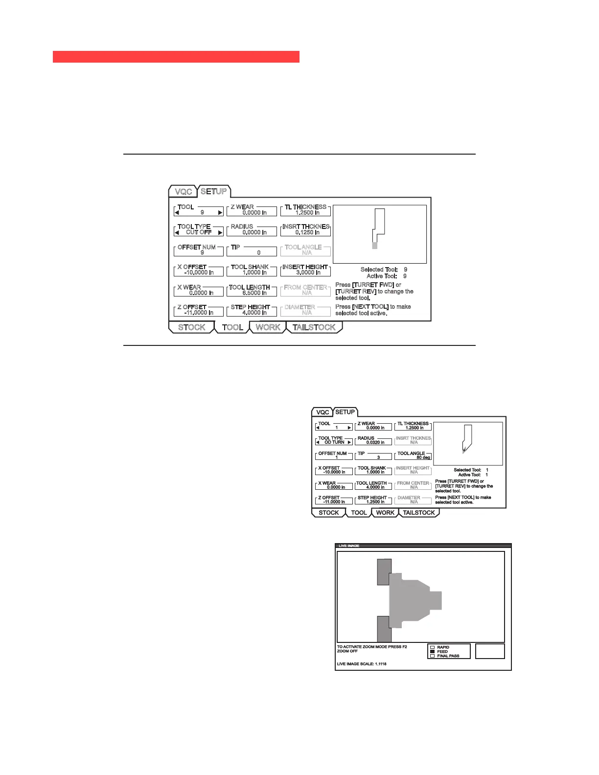
Tool data is stored in offsets in the IPS tabs. Live Image uses this information to draw and simulate the tool in
the cut. Required dimensions can be found in a tooling supplier’s catalog or by measuring the tool.
1. From the stock setup tab, press CANCEL, select the TOOL tab and press ENTER.
2. Select the tool number, type and enter the specic parameters required for that tool (i.e., offset number,
length, thickness, shank size, etc.).
NOTE: Setup parameter entry boxes are grayed out if they do not apply to the selected
tool.
TOOL
9
TOOL TYPE
CUT OFF
OFFSET NUM
X OFFSET
-10.0000 in
Z WEAR
RADIUS
TIP
0
TOOL SHANK
1.0000 in
TL THICKNESS
INSRT THCKNES
TOOL ANGLE
N/A
INSERT HEIGHT
3.0000 in
0.0000 in
VQC
SETUP
Selected Tool: 9
Active Tool: 9
STOCK TOOL WORK
X WEAR
0.0000 in
Z OFFSET
-11.0000 in
TOOL LENGTH
6.5000 in
STEP HEIGHT
4.0000 in
FROM CENTER
DIAMETER
1.2500 in
0.0000 in 0.1250 in
9
N/A
N/A
Press [TURRET FWD] or
[TURRET REV] to change the
selected tool.
Press [NEXT TOOL] to make
selected tool active.
TAILSTOCK
NOTE: Tool offset data may be entered for up to 50 tools.
The following section shows part of a lathe program that is cutting a piece of stock. The program is shown to
the left, while the appropriate tool settings are shown to the right.
O01000 ;
;
;
;
T101 ;
G54 ;
G50 S4000
G96 S950 M03 ;
M08 ;
G00 X6.8 ;
Z0.15 ;
G71 P80103 Q80203 D0.25 U0.02 W0.005 F0.025 ;
N80103 ;
G00 G40 X2.
G01 X2.75 Z0. ;
G01 X3. Z-0.125 ;
G01 X3. Z-1.5 ;
G01 X4.5608 Z-2.0304 ;
G03 X5. Z-2.5606 R0.25 ;
G01 X5. Z-3.75 ;
G02 X5.5 Z-4. R0.25 ;
G01 X6.6 Z-4. ;
N80203 G01 G40 X6.8 Z-4. ;
G00 X6.8 Z0.15 ;
M09 ;
M01 ;
G28 ;
M30 ;
T101 Settings
Part Worked from T101 Settings
 Loading...