74 Preventive Maintenance and Installation
P/N: SM-ACP215-01-EN(AB) Haemonetics
®
ACP-215
®
Service Manual
Diagnostic Testing
To power on the device in the Utilities mode of operation, press and hold
SHAKER while switching the power on. Continue to hold SHAKER until the
UTILITIES menu appears on the display.
Power Supply There is only one adjustment on the power supply and it is for the 5 volt supply.
Voltage levels must be set with a maximum load applied; therefore, it is
recommended that the supply is adjusted only after installation into the device.
The 5 volt supply voltage is pre-adjusted at the supplier and should require only
minor calibration. All outputs are protected against overload and short circuit.
Recovery is automatic when the fault is removed. The supply provides five DC
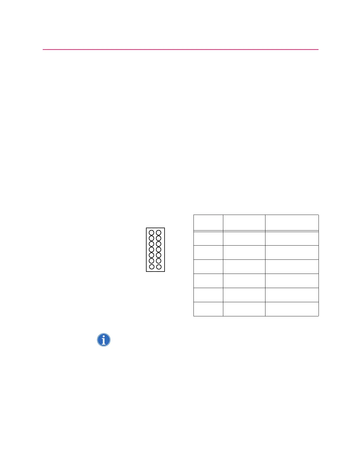
voltage levels, which can be measured on the backplane card at P507. See
Table 6 on page 74 for each pin definition.
See Figure 11 on page 34 for power supply illustrations.
The supply is cooled by a self-mounted fan; this improves the stability of the
voltage levels.
Printer Note: For information about installing the printer and/or loading the paper. See
“Printer installation” on page 3.
1. Turn the printer on by moving the slider switch located on the left-hand
side of the printer from the position marked “0” to the position marked “l”.
2. Ensure that the green online LED illuminates. See Figure 19 on page 75.
Table 6
Output P507 Voltage
1 Pins 8/9 +5.15 ± 0.03
2 Pin 10 + 15.0 ± 0.5
3 Pin 11 – 15.0 ± 0.5
4 Pins 12/13 + 28.4 ± 0.6
5 Pin 14 + 52 ± 5.0
6 Pins 1-7 Ground