Page 65
Side Mount Installation
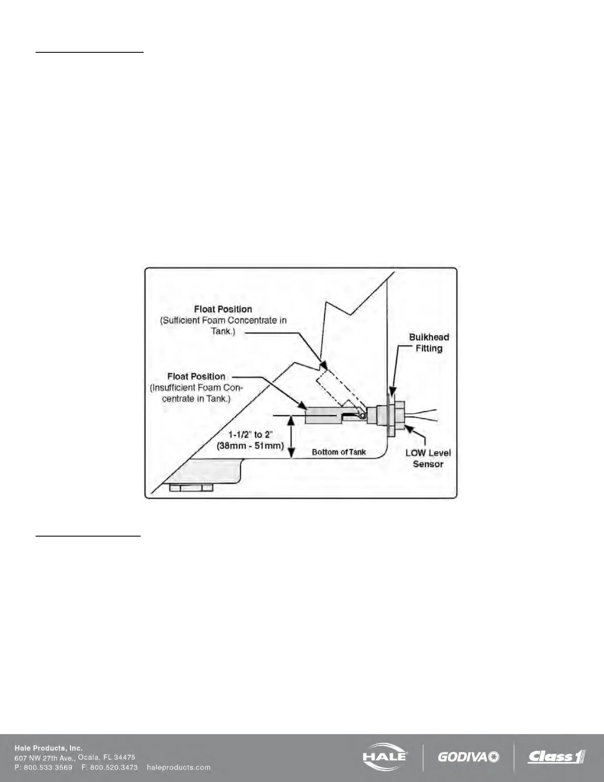
A side mount low tank level sensor is used if the bottom of the foam tank is not accessible.
1. The sensor has 1/2-in (13 mm) NPT threads. If tank design and construction allows, the side mount sensor is
threaded directly into the side of the tank at the proper height (Figure 53). Also, the sensor can be mounted on
the foam tank using a 1/2-in x 1” (13 x 25 mm) NPT bushing and a bulkhead fitting with 1” (25 mm) FNPT threads.
2. The center of the switch must be located at least 1-½ to 2 inches (38 to 51 mm) from the bottom of the foam tank
with the float positioned on top of the switch to allow up and down movement.
Note: When the side mount low level sensor senses a low concentrate condition the system operates for an addi-
tional one minute unless the foam concentrate level is restored. If the foam concentrate level is not restored the
system SHUTS DOWN. When locating the side mount low tank level sensor on the tank sufficient foam concen-
trate should be present for one minute of operation at the rated flow.
3. Coat the threads of the sensor with a suitable sealant and insert into tank fitting. Tighten sensor making sure the
float is on the top of the sensor (Figure 52).
4. After installation, check operation of the side mount low tank level sensor with a powered test light. With no foam
in the tank, the light should be ON. If light does not illuminate, rotate the side mount low tank level sensor until the
test light is ON.
Figure 53: Side Mount Sensor Location Dimensions
Top Mount Installation
The top mount low level sensor assembly is available for installations where the sides or bottom of the foam tank are not
accessible, or sensor service is required without draining the foam tank.
The sensor assembly is flange mounted in an access hole at the top of the foam tank. The two section telescoping as-
sembly permits adjustment of the low tank level sensor position for various foam tank depths from 31- 1/2-in to 60” (800
mm to 1,524 mm).
Flange cut-out dimensions are shown in Figure 54. The flange gasket can also be used as a template to mark hole loca-
tion.