Page 66
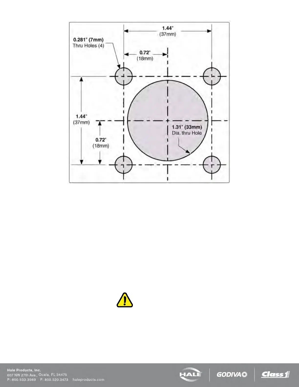
Figure 54: Top Mount Sensor Dimensions
1. Layout and drill holes in the top of the foam tank (Figure 54).
2. The center of the sensor should be located at least 1-1/2-in to 2” (38 to 51 mm) from the sides of the foam tank.
Note: The minimum depth of the foam tank for installation of the top mount sensor is 31-1/2-in (800 mm). If the
tank depth is less than 31-1/2-in (800 mm) cut the tubing accordingly. (See heading “Resizing the Top Mount
Low Level Sensor”).
3. Determine the approximate length of the low tank sensor extension by measuring from the top of the foam tank at
the flange opening to the bottom of the tank.
4. When properly installed the center of the sensor float should be 1-1/2-in to 2” (38 to 51 mm) above the bottom of
the foam tank.
5. Loosen the strain relief gland nut to allow the sensor wire to slide through the strain relief.
6. Adjust the telescoping section until the desired length is achieved as measured from the bottom of the flange to
the bottom of the sensor. Tighten the compression fittings on the union to lock length setting (Figure 55).
7. Tighten the strain relief around the sensor wire.
CAUTION!
USE MOUNTING HARDWARE THAT IS COMPATIBLE WITH ALL FOAM CONCENTRATES BEING
USED IN THE SYSTEM. USE WASHERS, LOCK WASHERS AND CAP SCREWS MADE OF BRASS
OR 300 SERIES STAINLESS STEEL.
8. Insert the sensor assembly through the 1.31” (33 mm) hole and align the screw holes on the flange and gasket
with the holes on the tank. Secure the assembly in place using four 1/4-20 UNC x 1” (25 mm) long cap screws,
1/4” (7 mm) washers and lock washers.