8 - Technical specifications
82
Electrical connections
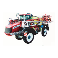
Road signalling
Wiring complies with Standard ISO 1724.
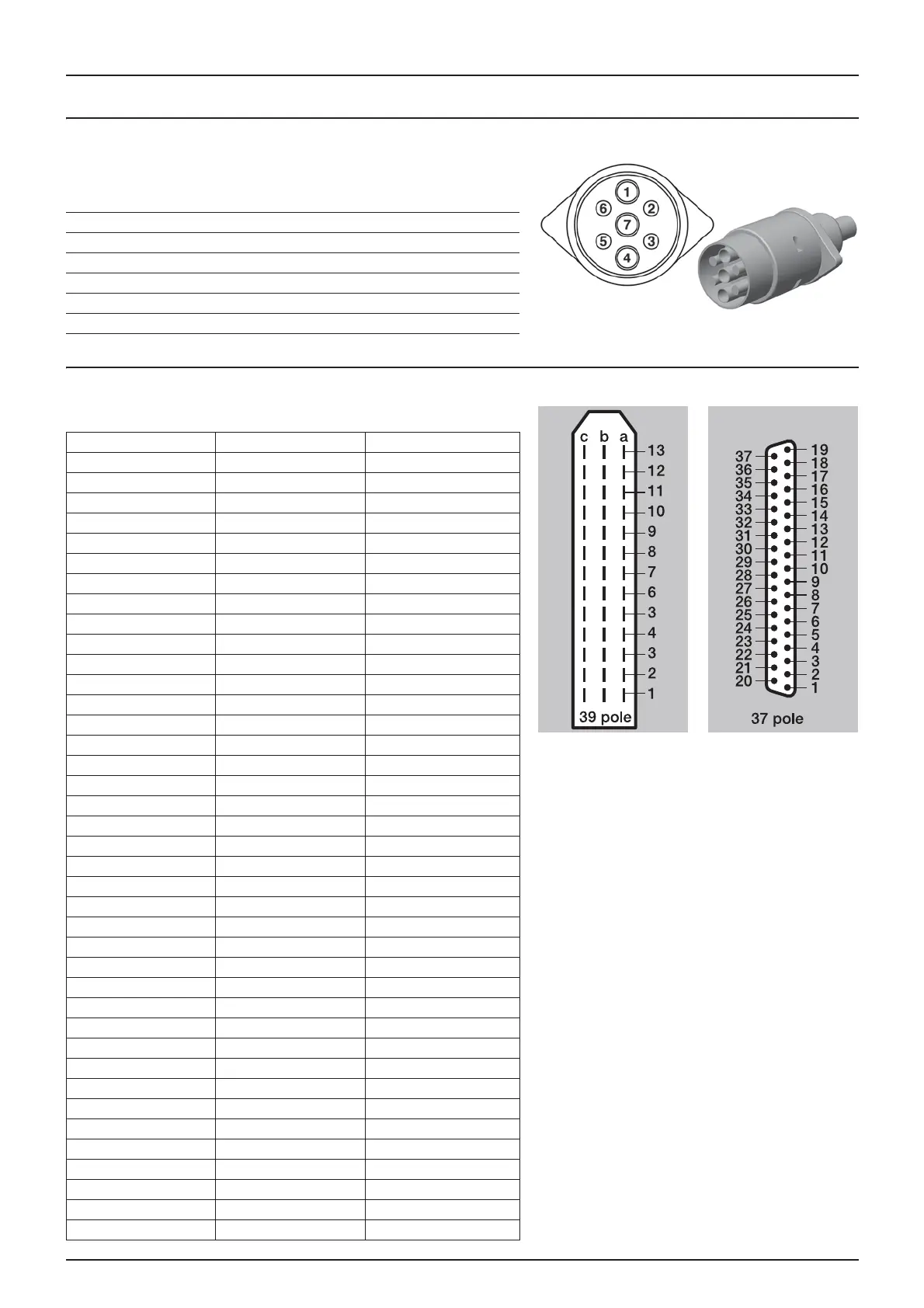
Spray II unit electrical connections
37 or 39-pin plug with cable.
Position Wire colour
1. Left indicator Yellow
2. Free Blue
3. Chassis White
4. Right indicator Green
5. Rear right position light Brown
6. Brake lights Red
7. Rear left position light Black
39 pins 37 pins Spray II
1a 5 S1+
1b 6 S1-
1c 26 Left end nozzle
2a 7 S2+
2b 8 S2-
2c 25 Right end nozzle
3a 9 S3+
3b 10 S3-
3c 29 +12V sensor
4a 11 S4+
4b 12 34-
4c 4 PWM 1TX
5a 14 S5+
5b 15 S5-
5c 27 Earth
6a 16 S6+
6b 17 S6-
6c 13 Option 5 regulation valve
7a 18 S7+
7b 19 S7-
7c 33 Option 1 4-20mA
8a 37 S8+
8b 36 S8-
8c 32 Option 2 Frq
9a 35 S9+/Air orientation 0-5V
9b 34 S9-/Turbine speed 0-5V
9c free Option 3/Tank gauge
10a 21 O/C+
10b 22 O/C-
10c free Output option PWM
11a 23 Pressure+
11b 24 Pressure-
11c 28 Flow
12a 20 Foam plugs 0-5V
12b 1 Option 4 Rx
12c 31 Speed
13a 3 TM L
13b 2 TM R
13c 30 Sensor (ground)
 Loading...