5-16 888-2463-001 3/6/08
WARNING: Disconnect primary power prior to servicing.
Diamond Series™
Section 5 Maintenance and Alignments
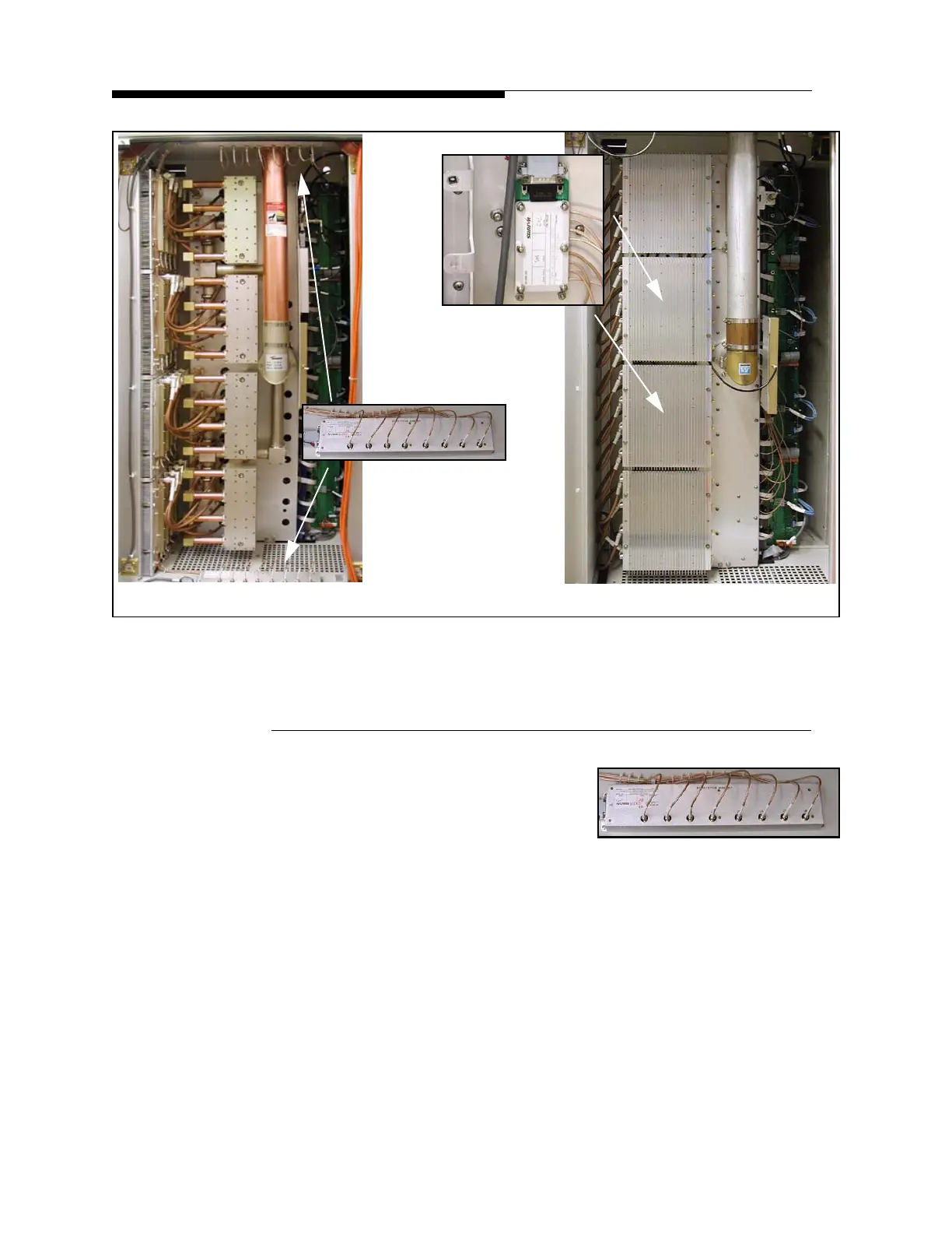
Figure 5-4 Cabinet Comparison
5.5.5.1 Old Style Reject Load Detector Calibration
STEP 1 Loosen the hardware holding the
detector in the cabinet and turn it over.
If necessary, allow it to swing free
being held by the RF Cables. Remove
the snap-on shields to gain access to the internal gain adjust switches.
STEP 2 Move JP1 on the RF detector to the TEST position, pins 2-3.
STEP 3 Select a cable (with adaptors if necessary) that will allow a direct
connection from the exciter SMA output to the detector input to be
calibrated.
STEP 4 First, set the exciter power to zero. Connect one end of the cable to the
exciter and the other end to the power sensor on the digital power meter.
STEP 5 Increase the exciter output until the digital power meter reads 50mW.
This will remove the effect of any line loss in the cable and assure
50mW is actually being applied to the detector.
(a) Old Style Combiner (b) New Style Combiner
Old Style Detector
New Detector
Located behind
Heatsink
 Loading...

