3/6/08 888-2463-001 2-7
WARNING: Disconnect primary power prior to servicing.
Section 2 Installation
Diamond Series™
2.5 RF Output Coax
!
CAUTION:
WHEN INSTALLING RF TRANSMISSION LINE OR AIR SYSTEM WIRING, DO
NOT STEP ON THE CONNECTORS OR THE ALUMINUM COVER PLATES ON
TOP OF THE CABINETS.
Because almost every station is different, refer to the Outline Drawings in Section 700
of the drawing package for information on location of hybrids, loads, couplers etc.
Install the directional couplers for each cabinet first, and work from there out toward the
loads and antenna. Be sure to make any desired VSWR measurements of the RF plant
before making final connections to the cabinets.
NOTE:
See Appendix A for general guidelines on how to cut and fit rigid transmission lines.
2.5.1 RF Line Optimization
Once the RF system and interconnecting transmission line are completed, it is
recommended that the system return loss be measured and adjusted if required. The
system should be optimized for at least a 30 dB return loss looking from the PA Cabinet
to the system load. System return loss can be adjusted with a fine-matcher line section.
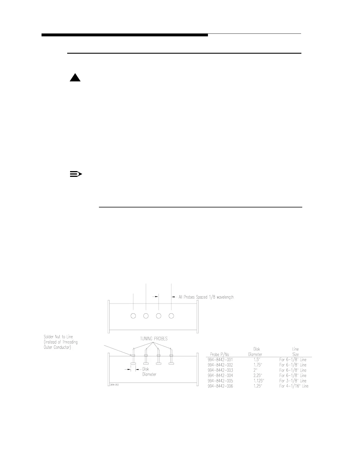
A fine matcher is a short section of rigid line with four adjustable tuning probes
(paddles) installed in it, see Figure 2-1.
Figure 2-1 Transmission Line Fine Matcher
 Loading...

