Connect the sensor to a cable
Connecting the TEDS chip:
In addition, there are two ways to connect the TEDS chip:
l
0-wire: TEDS chip is inserted between pins 2 and 7
l
1-wire: TEDS chip is inserted between pins 4 and 5
EMC-immune cabling
To have an EMC-immune cabling, a special wire assignment is used. See "Testing with high EMC immunity"
on page16 for more information.
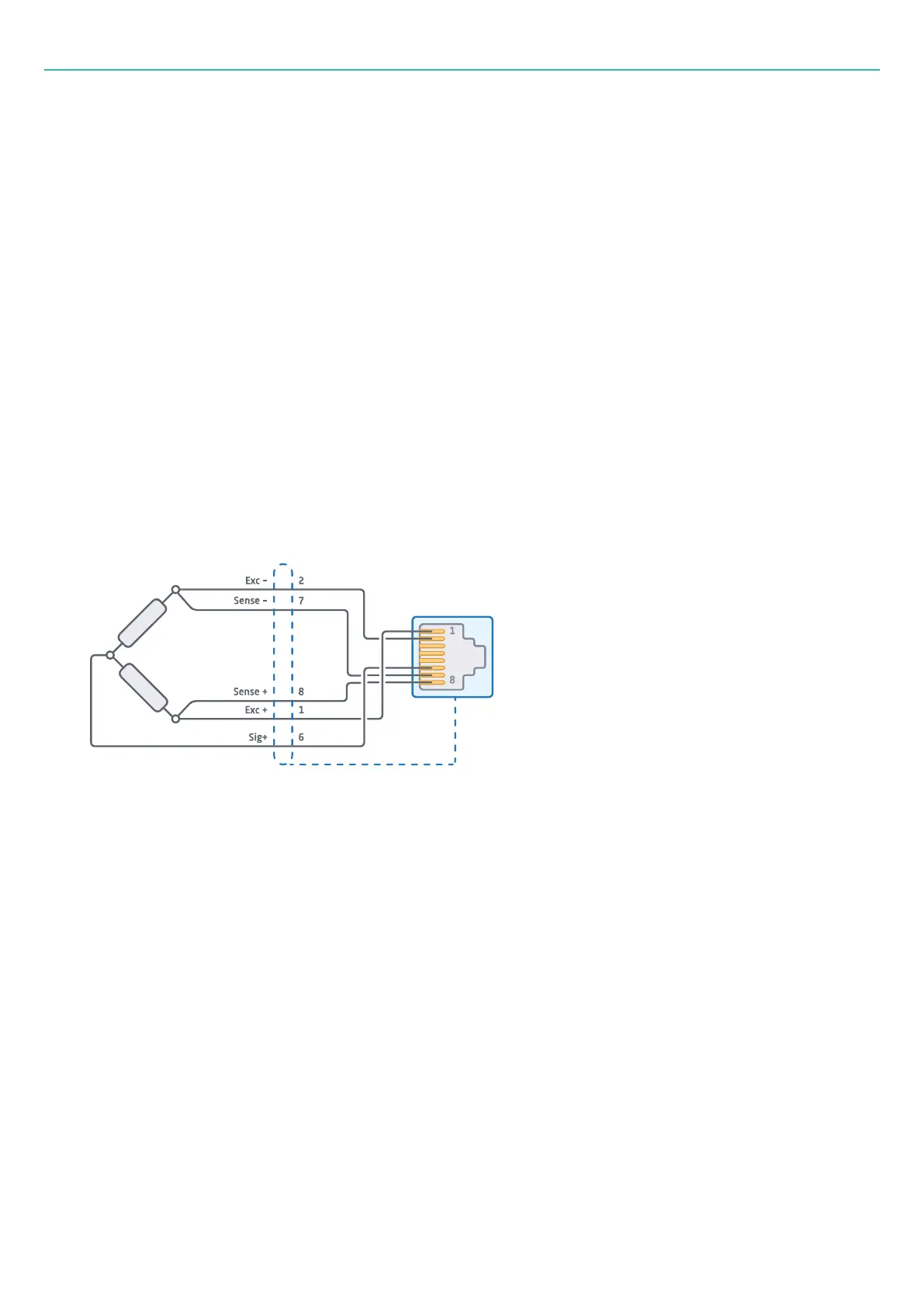
Half-bridge sensors (5-wire/3-wire)
Board type: B201-10
Connector type: 10×RJ45 (each with 8 pins)
Half bridges (resistive and inductive) can be connected in a 5-wire or 3-wire configuration. In a 3-wire
configuration, the two 'sense' lines are omitted. Both pin configurations are shown below.
5-wire configuration:
l
Pin 1: Excitation +
l
Pin 2: Excitation –
l
Pin 3: Not connected
l
Pin 4: Not connected (TEDS data)
l
Pin 5: Not connected (TEDS ground)
l
Pin 6: Signal +
l
Pin 7: Sense –
l
Pin 8: Sense +
3-wire configuration:
l
Pin 1: Excitation +
l
Pin 2: Excitation –
- 25 -