Figure 3-5 Insert Screw Socket
4. Align the 6 holes to the mounng plate with the drilled holes.
5. Route the cable through the cable hole of the
mounng plate, and connect to corresponding
external devices' cables.
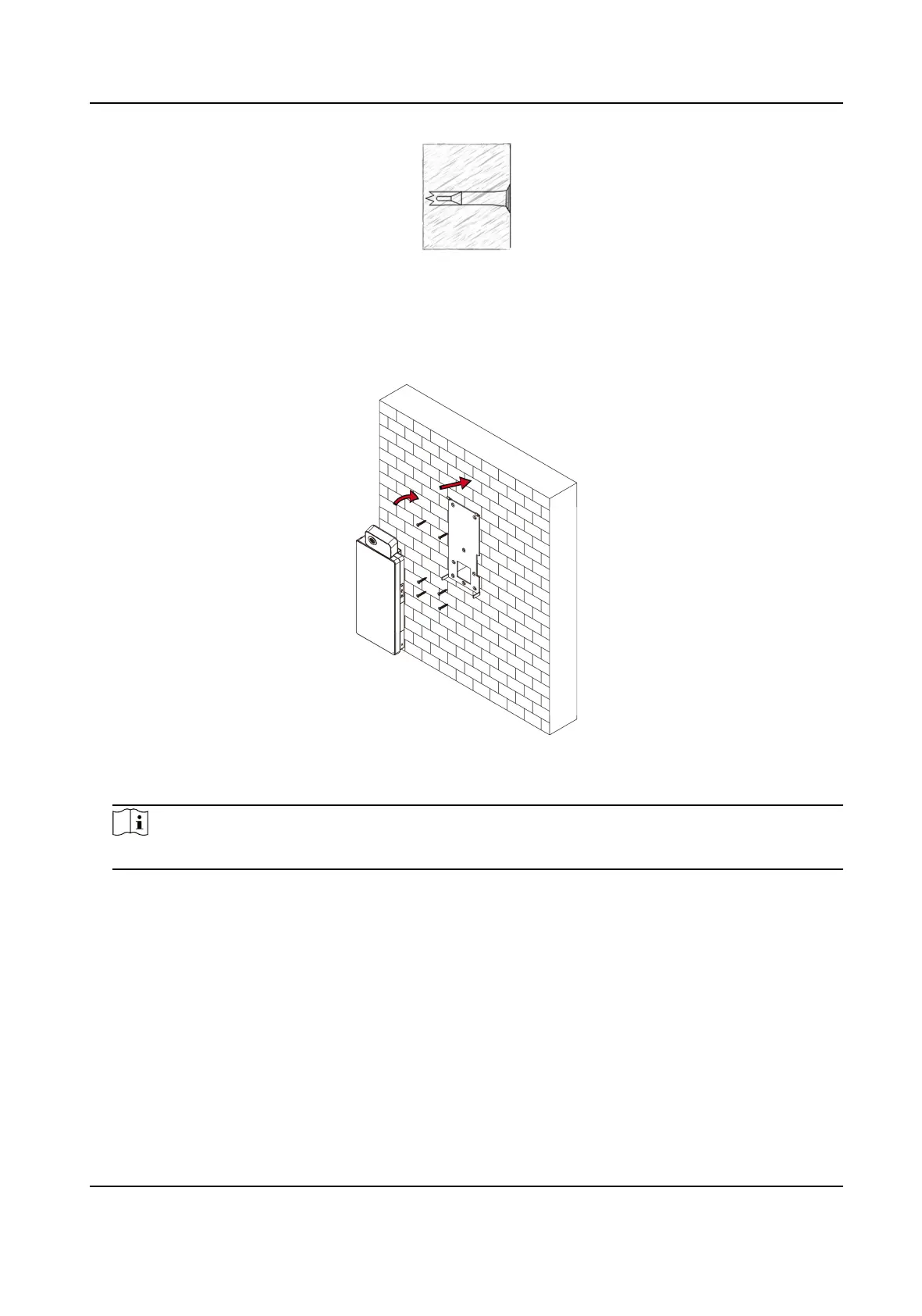
6. Align the device with the
mounng plate and hang the device on the mounng plate.
Figure 3-6 Install Device
7. Use 2 supplied screws (SC-M4×14.5TP10-SUS) to secure the device and the mounng plate.
Note
When the screw's head is beneath the device surface, the device is secured.
Face Recognion Terminal User Manual
8
 Loading...