6
────────────────────────────────────────────────────
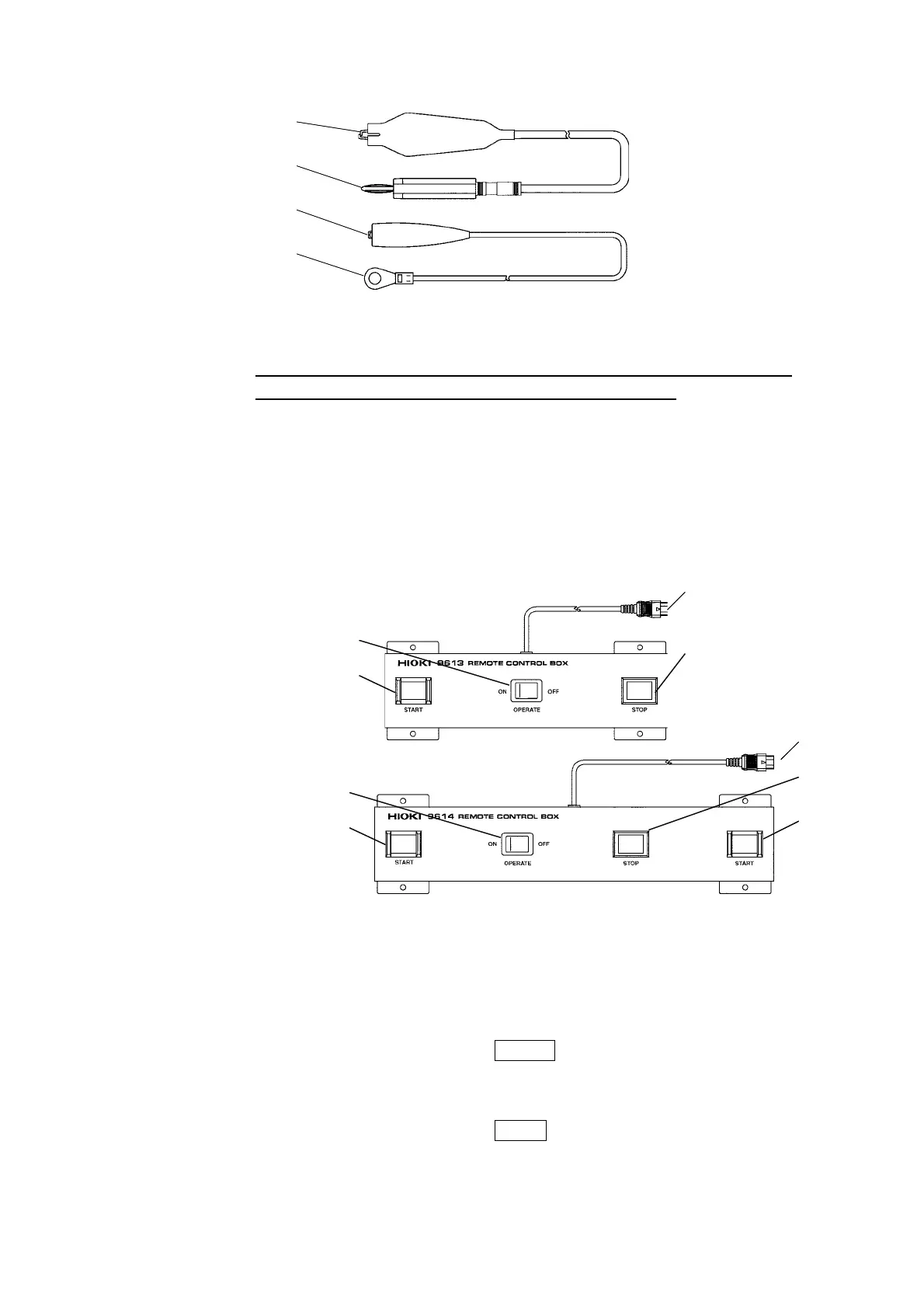
1.2 Names and Functions of Parts
────────────────────────────────────────────────────
1
2
1
3
Hi
h-volta
e side
red
Low-volta
e side
black
9614 REMOTE CONTROL BOX (DUAL)
9613 REMOTE CONTROL BOX (SINGLE)
1
2
4
3
1
2
4
3
2
9615 H.V. TEST LEAD
1 Alligator clip
Connect to a test point on the tested object.
Vinyl shield on 9615 H.V. TEST LEAD alligator clip is not high voltage
insulated. DO NOT touch when high voltage is applied.
2 High-voltage output plug
Connect to the HIGH terminal on the unit.
3 Low-voltage output plug
Connect to the LOW terminal on the unit.
REMOTE CONTROL BOX
1OPERATEswitch
Used to enable remote-control operation. When this switch is ON, the START and
STOP keys for remote control are active. Changing this switch during testing will
forcibly terminate the test.
2 START key
Works in the same manner as the
START
key on the unit. With the 9614
REMOTE CONTROL BOX (DUAL), the two START switches must be pressed.
3 STOP key
Works in the same manner as the
STOP
key on the unit. The STOP key is ON
during a test or when a voltage is being output.
4 Switch signal-line plug
Connect to the external switch terminal on the unit.