76
────────────────────────────────────────────────────
6.1 External I/O Terminal
────────────────────────────────────────────────────
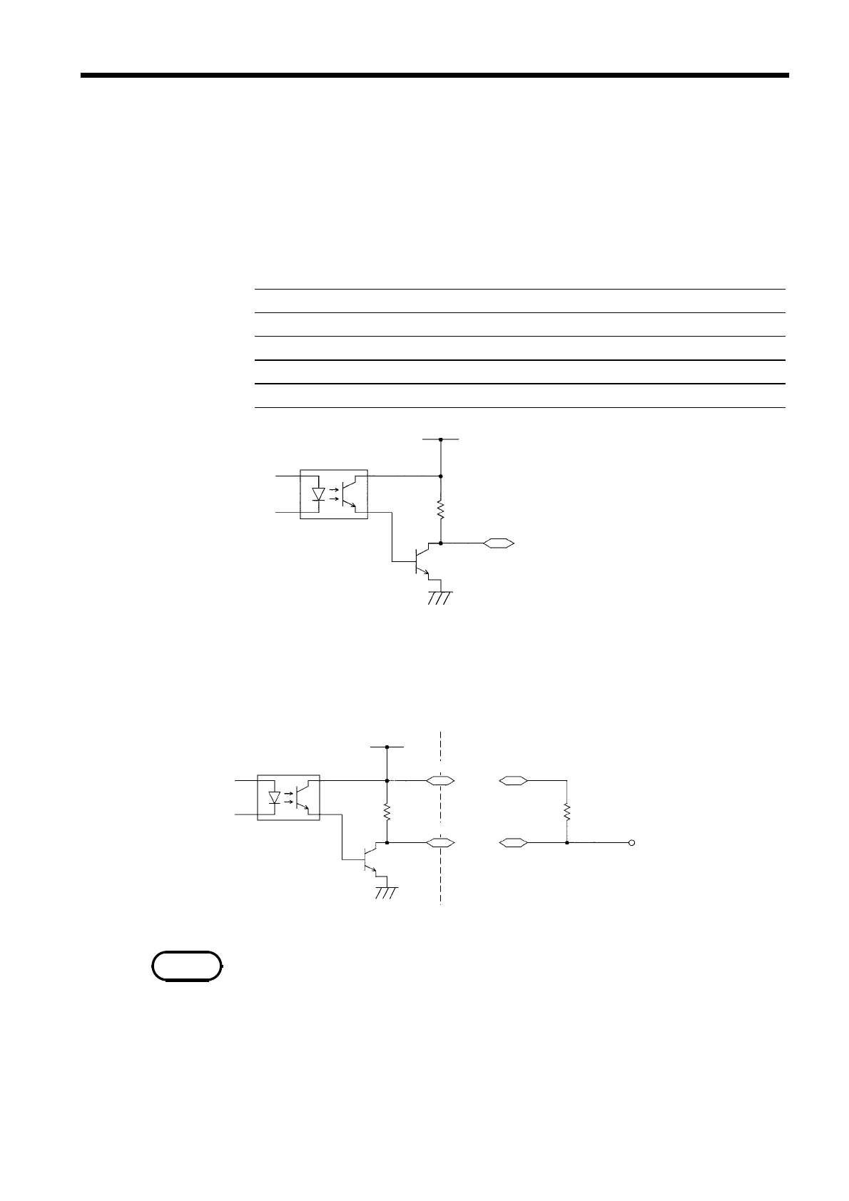
6.1.3 Example of Output Signal Connection
Output signal Open collector output
Max. load 30 VDC
Max. output current 100 mADC per signal
Output saturation voltage 1.5 VDC or less
Output signals HV-ON, TEST, PASS, UFAIL, LFAIL, READY
Photocou
ler
ISO.DCV
ISO.COM
External I/O Terminal
External I/O Terminal
ISO.DCV
ISO.DCV
Rela
Photocou
ler
ISO.COM
NOTE
The output signal becomes Lo depending on the condition of the unit. Prepare a
connector that conforms to the External I/O Specifications.
To enable the external I/O signal function, set the EXT-E signal (Pin 7) to Lo.
Connect the EXT-E signal to ISO.COM for the GND signal (Pins 15 to 18). An
output example is presented in 6.1.5, "Timing Chart of External I/O Terminal."
■
EXT I/O Output signals Specifications
(1) Controlling the relay (example)
To link the relay to an external device, make connections as shown below. Use
of the power supply ISO.DCV (Pins 33 to 36, 15 VDC 0.1 A) will facilitate the
connections.
・
A signal can absorb up to 100 mA.
・
When connecting an inductive load such as a relay, connect the diode in parallel
with the coil.