39
────────────────────────────────────────────────────
3.5 PASS or FAIL Determination
────────────────────────────────────────────────────
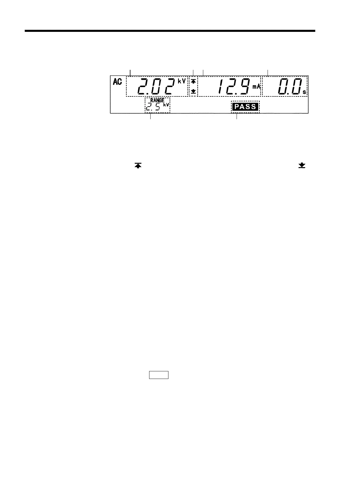
3.5.2 Screening in "PASS" State
1
2
3
4
5
6
(1) Measured voltage value
Indicates the voltage in the PASS state.
(2) Upper level value icon and Lower level value icon
The symbol
appears when the upper level value is set, and the symbol
appears when the lower level value is set.
(3) Measured current value
Indicates the value of the current flowing between the HIGH and LOW terminals
in the PASS state.
(4) Test completion time
Displays the time in which the test has been completed. In PASS state, 0.0s is
displayed.
(5) Output voltage range
Indicates the output-voltage range selected using the Range Selection switch.
(6) PASS
Indicates that the unit is in the PASS state.
Analog voltmeter
Indicates the voltage being output. The PASS Hold function cannot be used on the
analog voltmeter.
Danger lamp
Indicates that a voltage is being output. This lamp remains lit as long as a voltage
of at least 0.03 kV is being applied to the output terminal. It does not light up in
the READY state.
External I/O
The PASS
_______
signal is turned ON when PASS on the fluorescent indicator is lit. As
long as the PASS state is held, the PASS
_______
signal remains ON. The PASS
_______
signal is
turned OFF when the
PASS
light on the fluorescent indicator goes out. If voltage
remains in the output-voltage terminal following termination of a test, the H.V.ON
_________
signal remains ON. When the DANGER lamp goes out, the H.V.ON
_________
signal is
immediately turned OFF.