73
────────────────────────────────────────────────────
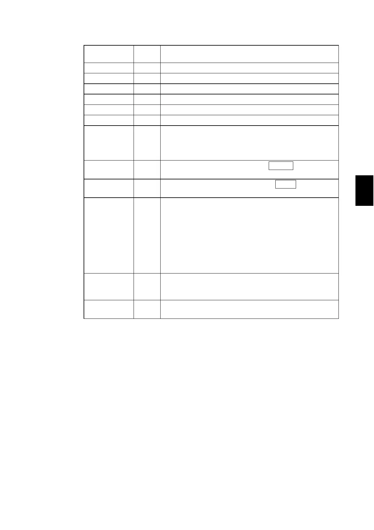
6.1 External I/O Terminal
────────────────────────────────────────────────────
1
2
3
4
6
8
9
10
11
12
13
14
A
Signal line
name
I/O Function
READY
-----------------------
OUT
_____
LO in the READY state
L-FAIL
---------------------
OUT
_____
LO in the FAIL state at LOWER (minimum value)
U-FAIL
---------------------
OUT
_____
LO in the FAIL state at UPPER (maximum value)
PASS
---------------------
OUT
_____
LO in the PASS state
TEST
---------------------
OUT
_____
LO in the TEST state
H.V.ON
________
OUT
_____
LO when a voltage is generated in the output terminal
EXT-E
_______
IN
At LO, the external I/O input signal is active.
INT.LOCK
____________
remains active regardless of this signal.
Changing this switch during testing will forcibly terminate
the test.
START
________
IN
LO is equivalent to pressing the unit
START
key and
provides the same functions.
STOP
______
IN
LOW is equivalent to pressing the unit
STOP
key and
provides the same functions.
INT.LOCK
___________
IN
Inter-lock function terminal. This signal is always active
regardless of the status of the EXT-E
_______
terminal.
When connected to ISO.COM, this terminal cancels the Inter-
lock function, enabling the unit to function properly. When
disconnected, the terminal disables all keys.
To activate the Inter-lock function, set the optional Inter-lock
function to "1: Set."
Use this terminal for a protective device against electric
shock that uses an area sensor or the like. See Section 6.1.4.
ISO.COM
---------------------
IN
Generates an internal GND for the unit.
Used temporarily to activate the external I/O function. Note
that the signal line is not insulated.
ISO.DCV
---------------------
OUT
Outputs a power voltage of 15 V (0.1 A), insulated from the
internal power supply.
Function of the signal line