79
────────────────────────────────────────────────────
6.1 External I/O Terminal
────────────────────────────────────────────────────
1
2
3
4
6
8
9
10
11
12
13
14
A
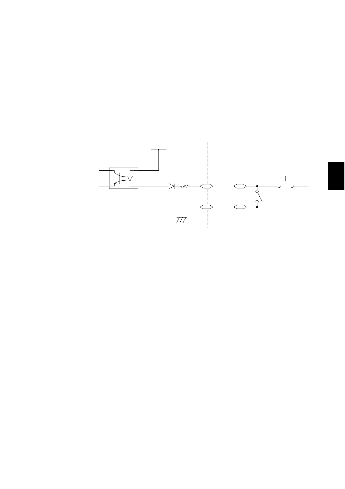
ISO.COM
2.2 kΩ
ISO.DCV
Settin
ad
ustment switch
Door switch
Photocou
ler
Connections for the inter-lock function (example)
For example, to ensure the safety of workers, the unit and the tested object are
placed in a box so that they are not in contact with each other. The door of the box
cover is also equipped with a switch that works in combination with the inter-lock
function. If a connection is made to the switch, the inter-lock function is enabled
when the box cover is opened. When the cover is closed, the function is disabled,
making the unit ready for testing.
All keys are inactive provided that the inter-lock function is active. As a result,
once the unit is mounted in the box, the settings cannot be changed. In such a case,
connect the setting adjustment switch the door switch such that these switches are
arranged in parallel, as shown below: