4.1 Comparator Function
51
4
Chapter 4 Applied Measurement
15
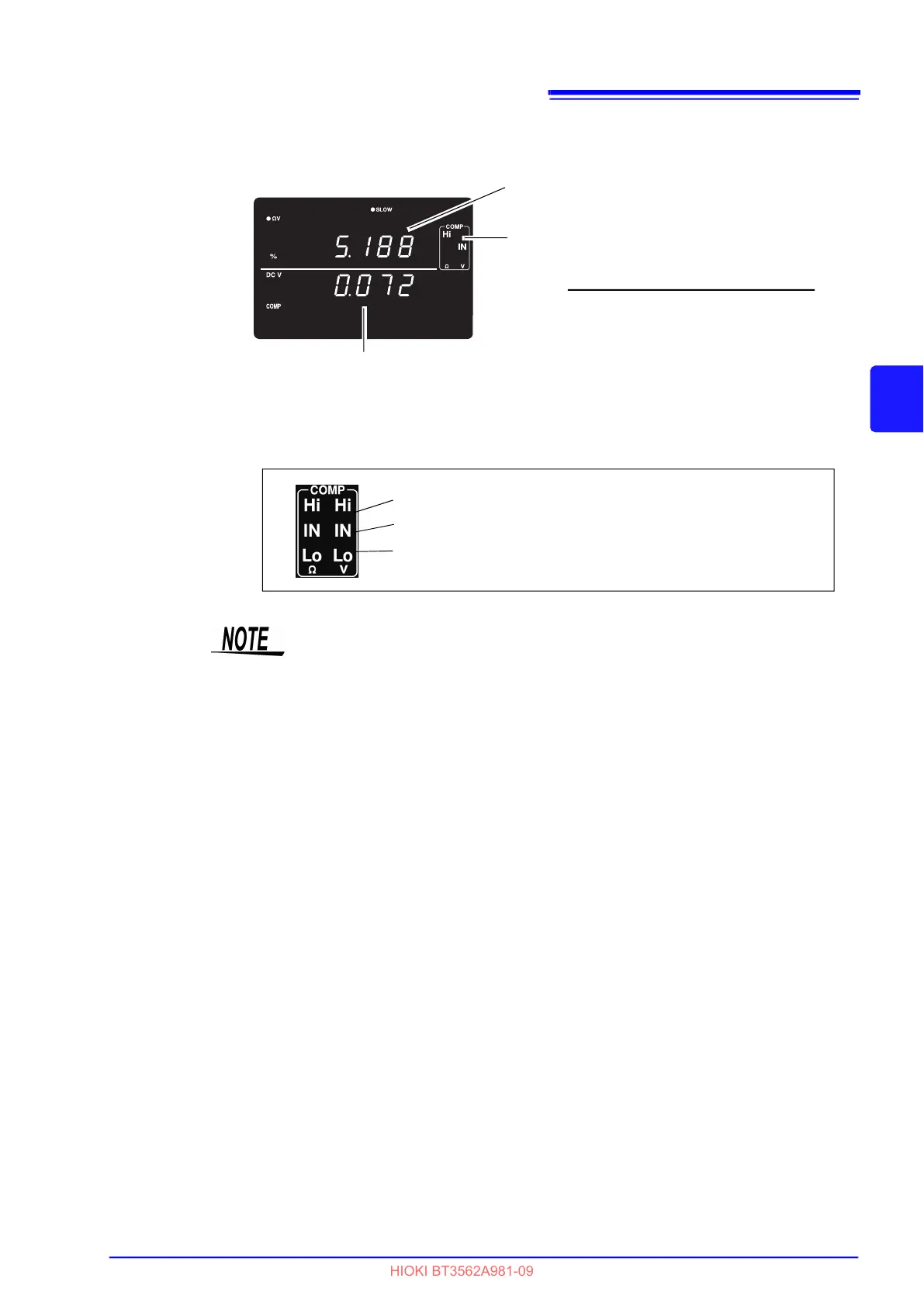
Connect a test object and judge the measured value.
In the V mode, you can verify comparator settings by pressing the VIEW key.
See " Switching Between Measurement Value and Comparator Setting Displays" (p.58).
Voltage measurements are displayed as their relative percentage offset
from the reference value (%)
Resistance measurements are displayed as
their relative percentage offset from the refer-
ence value (%)
Judgment Result
Measured resistance - Reference value
=
Reference value
× 100
Relative
percentage
Upper Threshold Value of setting range < Measured value
Lower Threshold Value of setting range Measured value Upper
Threshold Value of setting range
Measured value < Lower Threshold Value of setting range
The instrument can also base judgments on the absolute value of voltage mea-
sured values (to prevent Lo judgments when the positive and negative terminals
are connected backwards).
See "Configuring the Absolute Value Judgment Function (Voltage)" (p.55)