Appendix 1 Precautions for Making Custom Test Leads
A3
Appendix
.
×
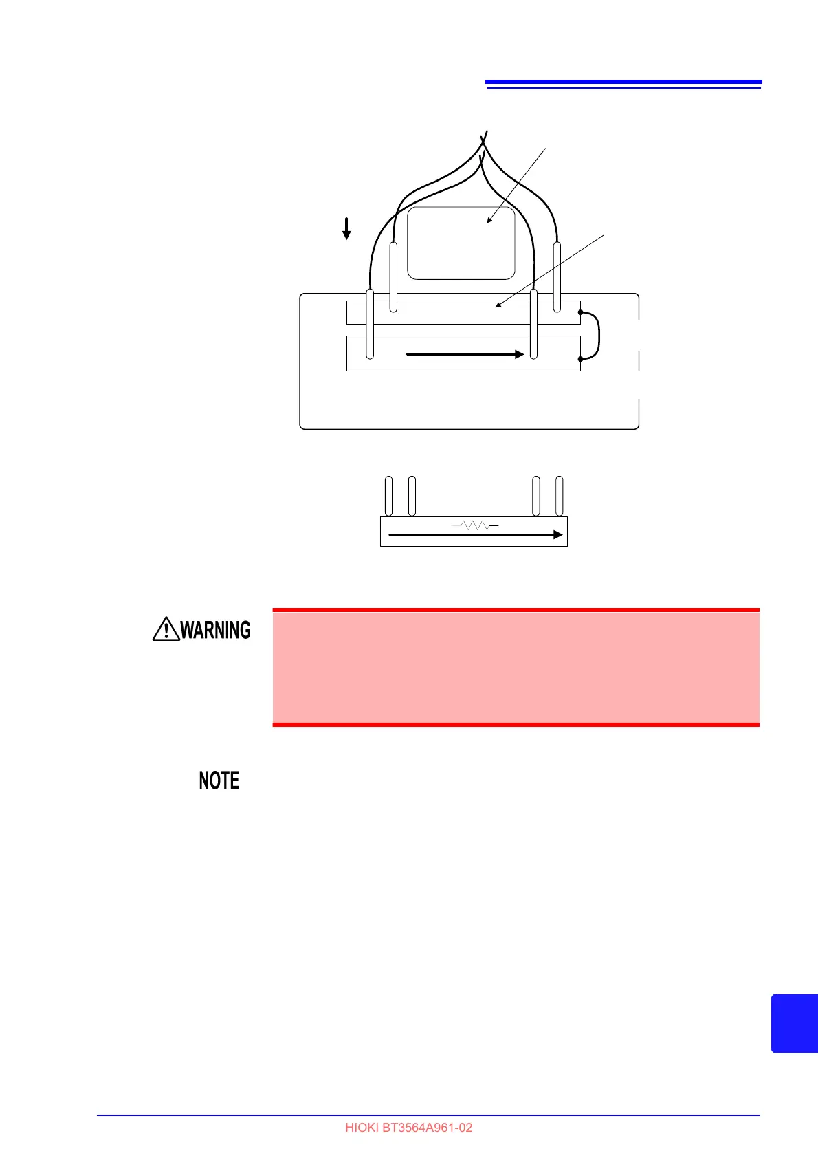
Probe pins
When current flows to the sense
conductor, a voltage corresponding to
the conductor's resistance occurs and
introduces an error component.
Source H
Sense H
Source L
Sense L
If you use a single copper plate (conductor),
the conductor's resistance will introduce an
error component.
← Voltage occurs →
Source H
Sense H
Sense L
Source L
Prevent the source current from flowing to the sense
conductor.
Connect the source and sense
conducting areas at a single
point.
Use a thick wire for the
source conductor to reduce its
resistance.
Sense
conductor
Source
conductor
・Loop area
・Loop shape
・Probe interval
・Wire placement (distance from
metallic parts on nearby equipment)
Zero-adjustment jig
• Do not touch the metallic tip of probes after measuring high-voltage batteries.
Doing so may result in electrical shock since internal instrument components
could retain a charge under those conditions. (Internal discharge time: Approx.
20 sec.)
• To avoid electric shock, use a cable whose withstand voltage is sufficiently
high relative to the battery voltage being measured.
• When separating the tips of the optional measurement leads, take care that
the SOURCE-H, SENSE-H, and SENSE-L shield wires do not come into
contact with the core wires. To avoid a measurement error when the instru-
ment detects a measurement anomaly, exercise care with regard to the
magnitude of the wiring resistance. It is recommended to use a stranded
cable with a conductor thickness of AWG 22 (0.3SQ) or greater.
• To avoid short-circuit accidents, connect the probe's banana terminals to the
instrument before connecting the probes to the battery.
 Loading...


