4.2 Trigger Function
57
4
Chapter 4 Applied Measurement
Two trigger sources are available: internal and external.
Measurement with
External Triggering
An external trigger can be applied in three ways.
• Applying a trigger manually by operating key
Pressing the TRIG key causes one measurement.
• Applying a trigger at the EXT I/O connector.
Shorting the TRIG
terminal to the ISO_COM of the EXT I/O connector on the
rear panel causes one measurement.
See " Input Signals" ( p.77).
• Applying a trigger through RS-232C or GP-IB interface
Sending the
TRG command via the RS-232C or GP-IB interface causes one
measurement.
4.2 Trigger Function
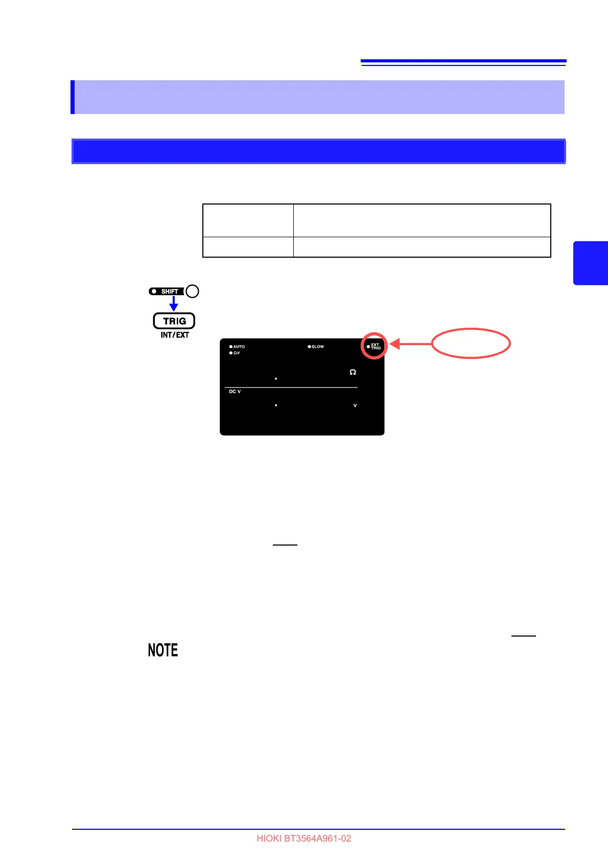
Trigger Source Settings
Internal Trigger Trigger signals are automatically generated internally.
(free-run)
External Trigger Trigger signals are provided externally or manually.
(The SHIFT indicator lights up.)
Switches the selected trigger source.
EXT.TRIG lit................. External triggering is selected.
EXT.TRIG not lit........... Internal triggering is selected.
• When Internal triggering is enabled, external input at the EXT I/O TRIG termi-
nal and the
TRG command are ignored.
• The normal state of operation with the front panel controls is continuous mea-
surement. Setting the trigger source to Internal enables the free-run condition
in which triggering occurs continuously. When the trigger source is set to
External, a measurement occurs each time an external trigger is applied. Con-
tinuous measurement can be disabled via RS-232C or GP-IB interface sig-
nals, in which case triggering occurs only when signaled by the external host
(PC or PLC).
See " Triggering System Description" ( p.145).