Appendix 4 Synchronous Detection System
A6
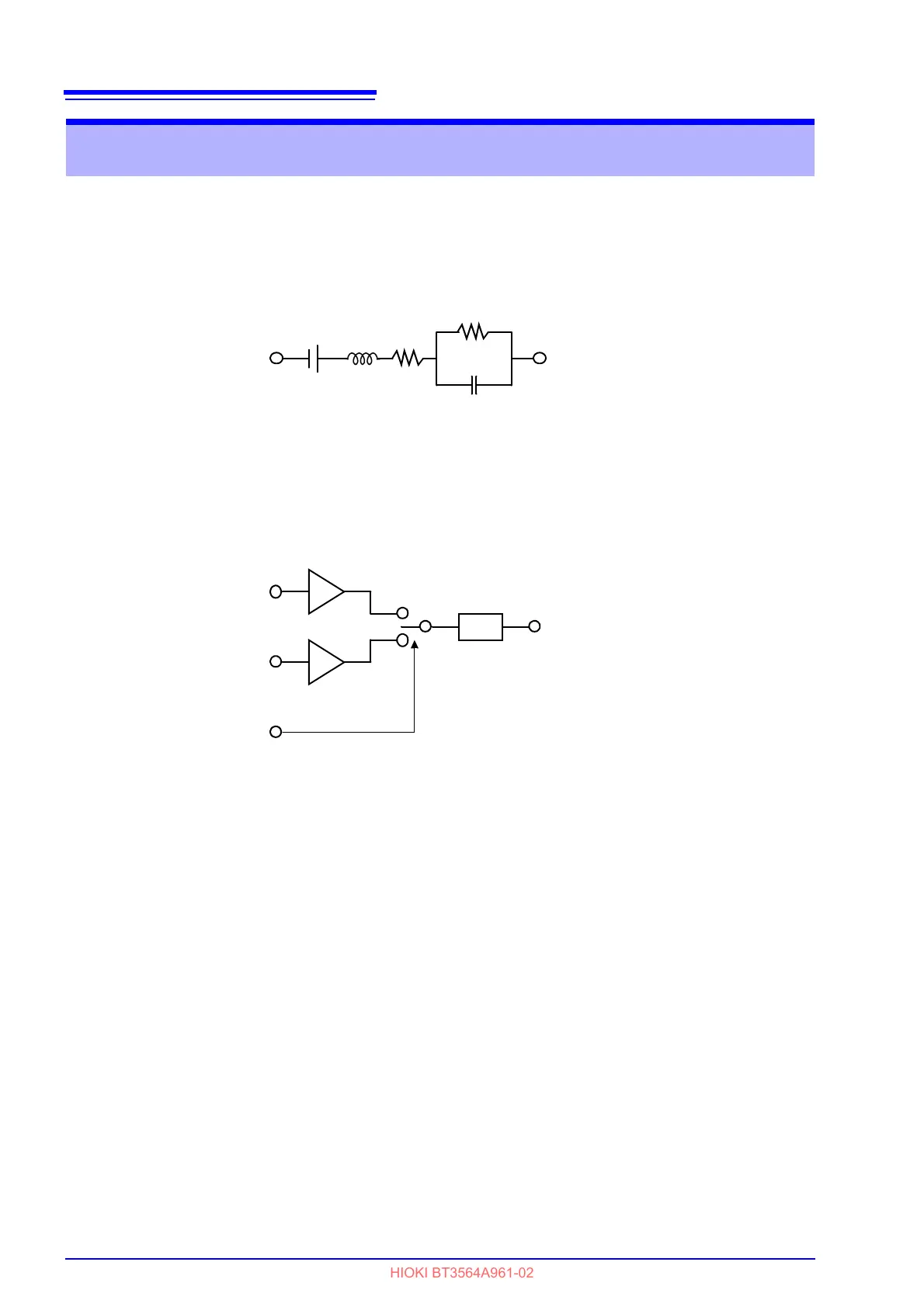
The figure below shows an equivalent circuit for a battery. If the measured object
exhibits other electrical characteristics in addition to resistance, as shown in this
figure, we can use the synchronous detection system to obtain the effective
resistance of the object. This synchronous detection system is also used to sep-
arate faint signals from noise.
The synchronous detection system picks up the reference signal and those sig-
nals having the same phase components. The figure below gives a simplified
schematic diagram of the synchronous detection system. The system consists of
a multiplying circuit that multiplies two signals and a low-pass filter (LPF) that
picks up only DC components from the output.
Given "v1," a reference signal voltage for the AC current generated in the instru-
ment, and "v2," the signal voltage for use in synchronous detection, these
parameters may be expressed by the equation given below.
of v2 shows the
phase difference against v1 and is generated by the reactance.
v1 = Asin
t
v2 = Bsin (
t + )
When synchronous detection is applied to both v1 and v2, they are expressed as
follows:
v1 X v2 = 1/2ABcos
- 1/2ABcos (2t + )
The first term indicates effective resistance. The second term is attenuated by
the LPF. The instrument displays the first term.
Appendix 4 Synchronous Detection System
Non-Inversion amplifi-
Inversion amplifi-
Reference Signal
-1
Low-Pass Filter
+1
LPF