3.6 Zero-Adjust Function
31
3
Chapter 3 Measurement
Executing Zero-Adjustment
1
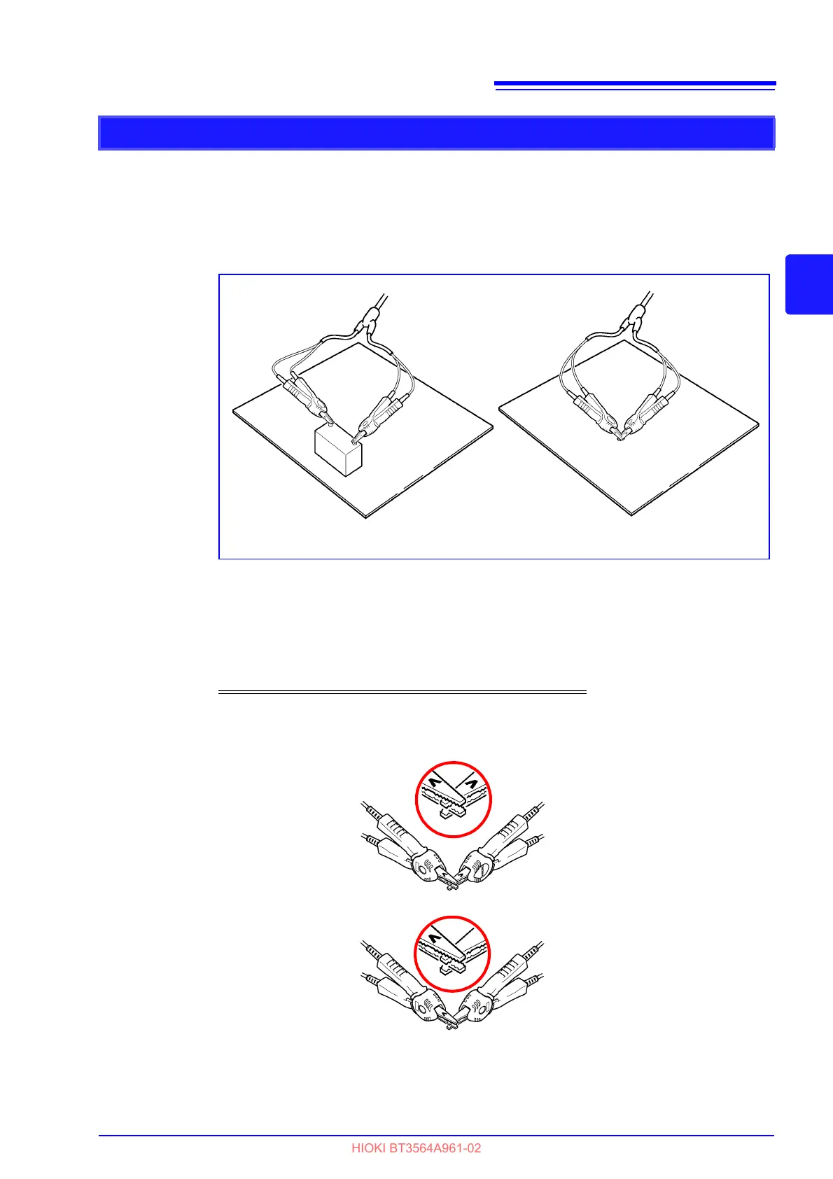
Position the measurement leads in the actual measurement state.
Since the amount of zero adjustment varies with the position and state of the mea-
surement leads (probes) (i.e., their length, shape, position, etc.), the measure-
ment leads must be positioned in the actual measurement state before performing
zero adjustment.
These variations are particularly pronounced in the 3 m and 30 m ranges, so
be sure to position the leads in same state as will be used to perform actual mea-
surement when using those configurations.
2
Short-circuit the test leads together.
Proper zero adjustment is not possible with incorrect wiring.
Example: Model L2107 Clip Type Leads
at zero adjustment at measurement
Red
SOURCE
SOURCE
SOURCE
SENSE
SENSE
SENSE
Correct
Incorrect
Red
Black
Black
SOURCE
SENSE
Bring the "V" marks together at the
same position.