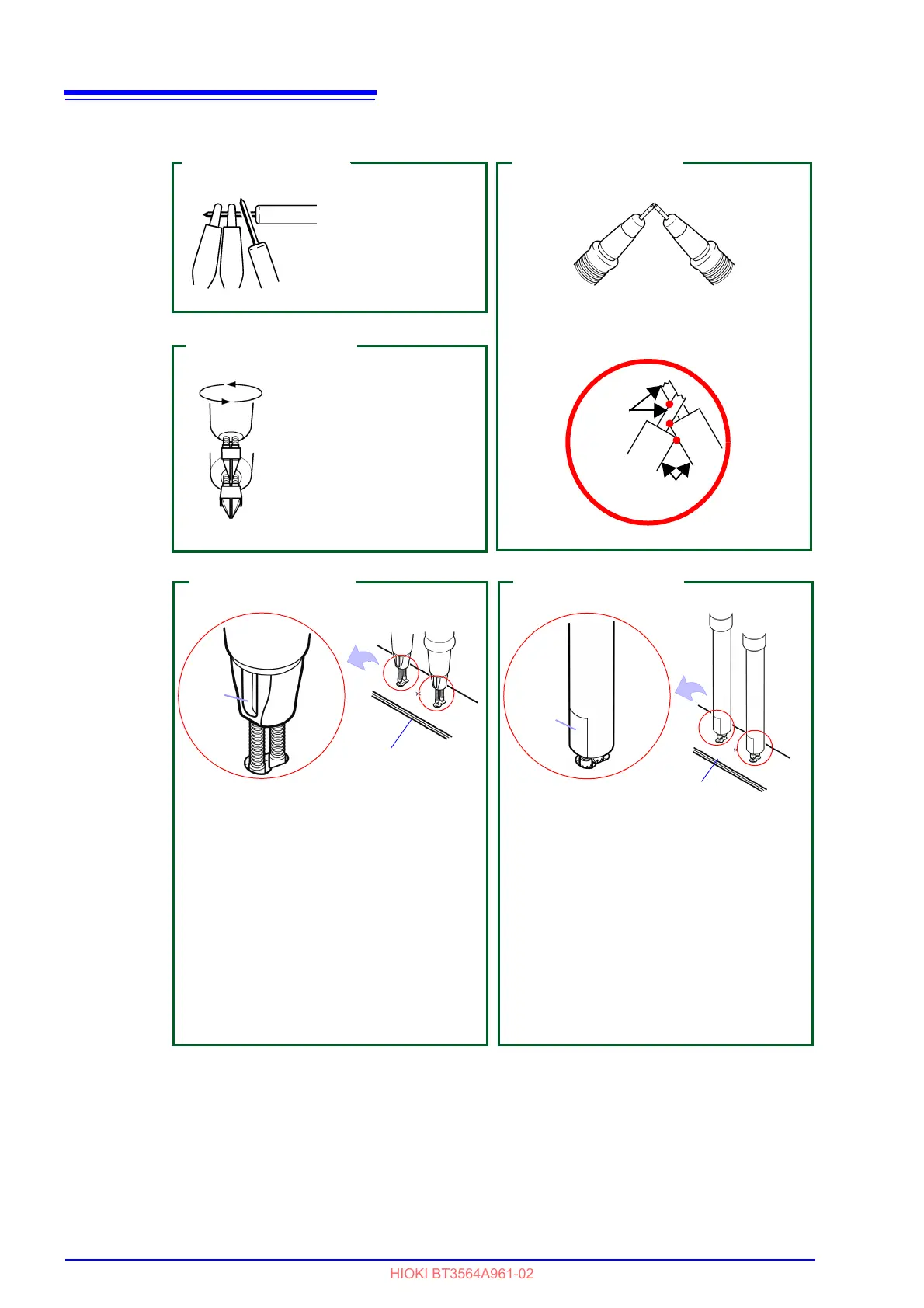
Model 9453 (Option)
Perform zero adjust-
ment with the alligator
clips and lead rods
placed as above.
Model 9771 (Option)
When the measured resis-
tance value is displayed
as "-----", change the fac-
ing direction.
Let the two points of the
pin tip touch the spring
part perpendicularly (be
careful not to short-circuit
the springs).
External conductor
Bring the pins into contact at 3 points to
perform zero adjustment.
Internal
conductor
Model 9770 (Option)
Line
Each sense pin has a line affixed to its base.
When using the zero-adjust feature, orient
the test lead so that the surface the same di-
rection.
Choose a hole suited to the distance be-
tween the terminals on the battery subject to
measurement and hold the test lead against
the zero-adjust board so that it remains
symmetrical to the central plus sign (+) on
the board. While inserting each SENSE (the
side with a line) pin into the larger side of
each elongate hole.
Model L2100 (Option)
Model Z5038 0 ADJ Board
Flat
The sense side of the tip of the test lead has
a flat surface. When using the zero-adjust
feature, orient the test lead so that the sur-
face the same direction.
Choose a hole suited to the distance be-
tween the terminals on the battery subject to
measurement and hold the test lead against
the zero-adjust board so that it remains
symmetrical to the central plus sign (+) on
the board. While inserting each SENSE (the
side with the surface) pin into the larger
side of each elongate hole.
Model L2110 (Option)
Model Z5038 0 ADJ Board
surface