4.1 Comparator Function
45
4
Chapter 4 Applied Measurement
This example describes the comparator setting method.
• The upper and lower thresholds are saved as the displayed counts (indepen-
dent of measurement mode and range). Therefore, changing the measure-
ment mode or range results in the same display counts representing different
absolute values.
Example:
To specify the lower threshold as 150 m
in the 300 m range, enter “15000”.
Switching to the 3
range after making this setting changes the lower thresh-
old to 1.5
.
• The instrument can also base judgments on the absolute value of measured
voltage values (to prevent Lo judgments when the positive and negative termi-
nals are connected backwards).
See "Configuring the Absolute Value Judgment Function (Voltage)" ( p.53)
Comparator Setting Example 2 (Reference Value and Tolerance Judgment)
Example:
Set a reference value and tolerance in the V mode (3 range), and set the beeper
to sound while measured values are within tolerance.
Resistance : Reference value 1.5 , Tolerance 5%
Voltage : Reference value 4.2 V, Tolerance 0.5%
1
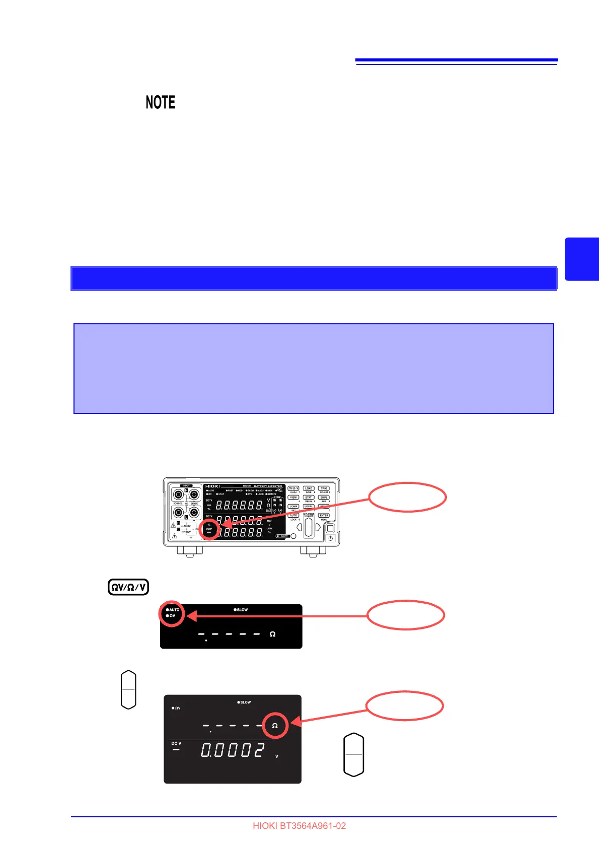
Confirm that the Comparator function is off.
(The settings cannot be changed while the Comparator function is enabled. Press the
COMP key to disable the Comparator function.)
2
Select the V measurement mode.
3
Select the measurement range (for this example, the 3 range).
Increase the resistance measurement range.
Decrease the resistance measurement range.
lit