OPERATOR'S STATION
1-25
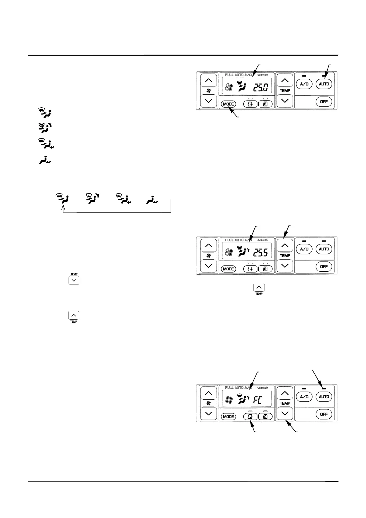
Control Panel Designation and Function
•
Mode Switch (14):
Selects the air vent. The selected air vent is indicated
on LCD (7).
Air flows out of front vent and the defroster
vents.
Air flows out of the front and rear vents and
the defroster vents.
Air flows out of the front and foot vents and
the defroster vents.
Air flows out of the foot vents.
Each time mode switch (14) is pressed, the vent location
can be changed in four stages as illustrated below.
AUTO
o
o o o
•
When AUTO switch (9) is selected the AUTO, the air
vent location is automatically selected.
x
Temperature Control Switch (11):
Sets temperature in the cab from 18.0 to 32.0
q
C or 63 to
91
q
F by 0.5
q
C or 1
q
F step. The set-temperature is dis-
played on LCD (7).
•
FC (Full-Cool)
Push the
button after setting air temperature to
18
q
C (63
q
F). Air flow temperature is set to the lowest
and the “FC” symbol is displayed on LCD (7).
•
FH (Full-Heat)
Push the
button after setting air temperature to
32
q
C (91
q
F). Air flow temperature is set to the highest
and the “FH” symbol is displayed on LCD (7).
•
When the AUTO indicator is ON, air temperature at
the vents is automatically set together with the blower
speed and vent locations.
•
When the AUTO indicator is OFF, only air temperature
at the vents is automatically set.
•
When the “FC” symbol is displayed on LCD (7), air
temperature at the vent, air vent (front and rear vents)
locations, recirculation air suction port, and blower
speed are maintained at the lowest cooling conditions.
However, in case the circulation indicator is ON before
the “FC” symbol is displayed, circulation operation is
maintained.
M178-01-074
Display when AUTO switch (9) is pressed:
M178-01-075
Display when the button is pressed
after displaying 25.0
q
C (77
q
F).
M178-01-076
Display when the LCD displays
ª
FC
¼
symbol.
14
7
11
7
11 9
AUTO Indicator
9 7