EOS
|
HD OPERATION
60
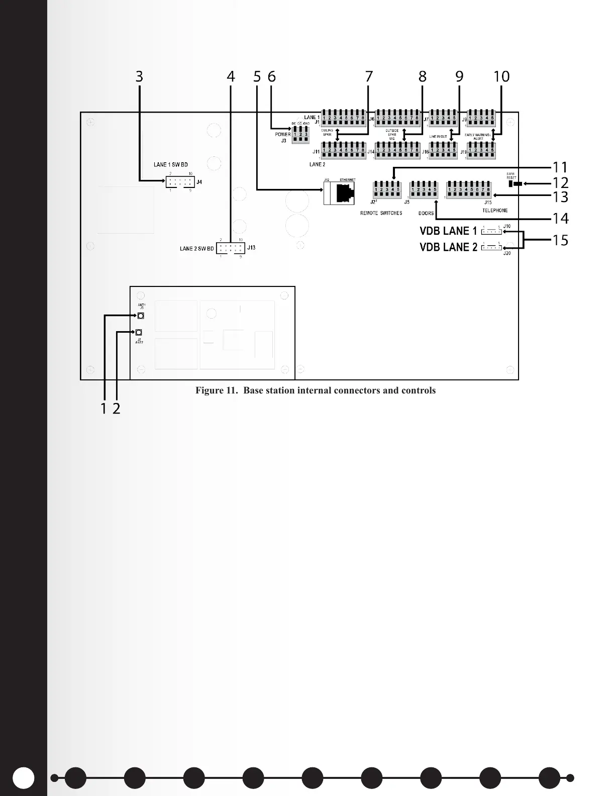
Base Station Internal Connectors and Controls
Figure 11. Base station internal connectors and controls
1. ANT1 antenna connector
2. ANT2 antenna connector
3. Switcher board connectors, J4-Lane 1
4. Switcher board connectors, J13-Lane 2
5. Ethernet connector, J12
6. Power connector, J3
7. Ceiling speaker connector, J1-Lane 1, J11-Lane 2
8. Outside speaker/microphone connector, J6-Lane 1, J14-Lane 2
9. Line in/out connector, J7-Lane 1, J16-Lane 2
10. Early warning/alert connector, J9-Lane 1, J19-Lane 2
11. Remote switch connector, J2
12. Reset switch
13. Telephone connector, J15
14. Doors connector, J5
15. Vehicle detector board (VDB) connector, J10-Lane 1, J20-Lane 2
1 2 3 4 5 6 7 8 9
Introduction
EOS|HD
Equipment
EOS|HD
Operation
Audio Processing
Functions
Equipment Care
and Cleaning
Troubleshooting
Equipment
Specications
EOS|HD Message
Center Guide
Important
Notices
 Loading...