9-27
1
2
3
4
5
6
7
8
9
10
11
12
13
14
15
16
17
18
19
20
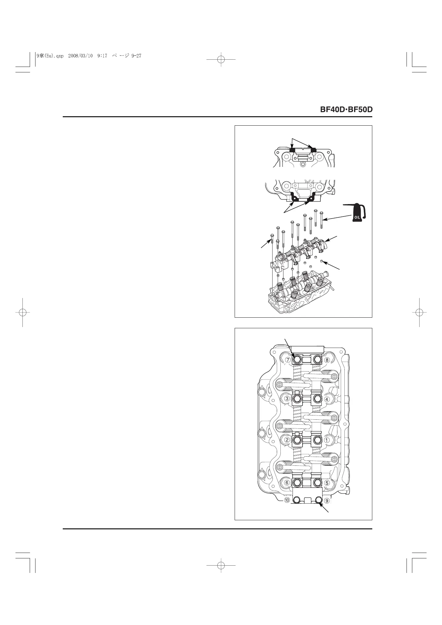
9) Clean the parts of the cylinder head where the No.1 and
No.4 cam holders are installed thoroughly using the
degreasing cleaning solvent.
10) Apply beads of liquid gasket (ThreeBond
®
#1141C or
equivalent) to the indicated area of the cylinder head
(where the No.1 and No.4 cam holders are installed).
11) Apply molybdenum disulfide oil to the rocker arm/camshaft
contact surfaces.
12) Set the eight 8 x 14 mm dowel pins on the cylinder head
assembly, and install the rocker shaft assembly on the
cylinder head assembly.
Remove the eight 6 x 70 mm flange bolts once from the
cam holders.
13) Apply engine oil to the threads and seat of the 6 x 70 mm
flange bolts, and loosely tighten the eight 6 x 70 mm flange
bolts and the two 6 x 35 mm flange bolts against the cam
holder.
14) Tighten the eight 6 x 70 mm flange bolts and the two 6 x 35
mm flange bolts in two or three steps in the numbered
sequence shown. Tighten to the specified torque.
TORQUE:
6 x 70 mm flange bolt: 14 N
.
m (1.4 kgf
.
m, 10 lbf
.
ft)
6 x 35 mm flange bolt: 12 N
.
m (1.2 kgf
.
m, 9 lbf
.
ft)
[1]
LIQUID GASKET APPLICATION AREA
[1]
LIQUID GASKET
APPLICATION AREA
[2]
ROCKER
SHAFT
ASSEMBLY
6 x 35 (2)
[3]
8 x 14 mm
DOWEL
PIN (8)
6 x 70 (8)
6 x 35 (2)
6 x 70 (8)