Light blue White/black Light green
UP (Up)
Neutral
DN (Down)
15-8
1
2
3
4
5
6
7
8
9
10
11
12
13
14
15
16
17
18
19
20
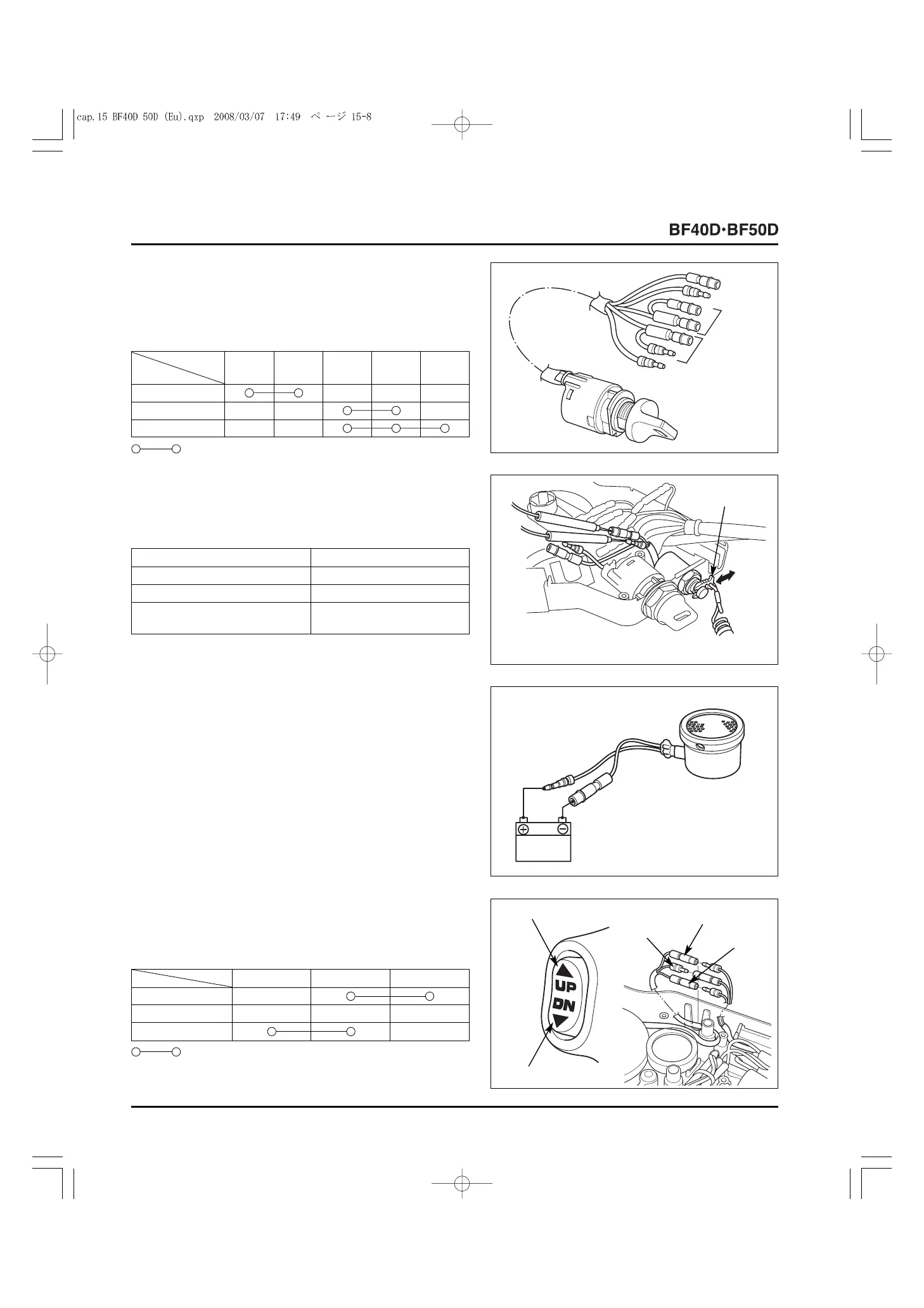
3. INSPECTION
• COMBINATION SWITCH
Check for continuity between the terminals with the switch in
each position.
Wire E IG BAT LO ST
Position (Bl) (Bl/R) (W/Bl) (Bl/Y) (Bl/W)
OFF (Stop)
ON (Run)
START (Start)
: Continuity
If there is any abnormality, replace the switch with a new one.
Replace the switch with a new one if it is not normal.
• EMERGENCY STOP SWITCH
Attach the tester leads to the terminals and check for
continuity.
Switch clip position Continuity
Set No
Not set Yes
Switch is pushed with switch
Yes
clip being set
Bl/W
Bl/R
Bl/Y
W/Bl
Bl
[1]
SWITCH CLIP
• WARNING BUZZER
• Use a known-good battery.
Connect the black/yellow terminal of the warning buzzer to the
battery positive (+) terminal, and the yellow/green terminal to
the battery negative (
-
) terminal as shown. Check that the
buzzer sounds this time.
If it does not, replace the buzzer with a new one.
12 V
• POWER TRIM/TILT SWITCH [POWER TRIM/TILT
TYPE ONLY]
Check for continuity between the terminals with the switch in
each position.
: Continuity
If there is any abnormality, replace the switch with a new one.
[1] UP (Up)
[2]
DN (Down)
[4]
LIGHT GREEN
[3]
WHITE/
BLACK
[5]
LIGHT
BLUE