7-18
1
2
3
4
5
6
7
8
9
10
11
12
13
14
15
16
17
18
19
20
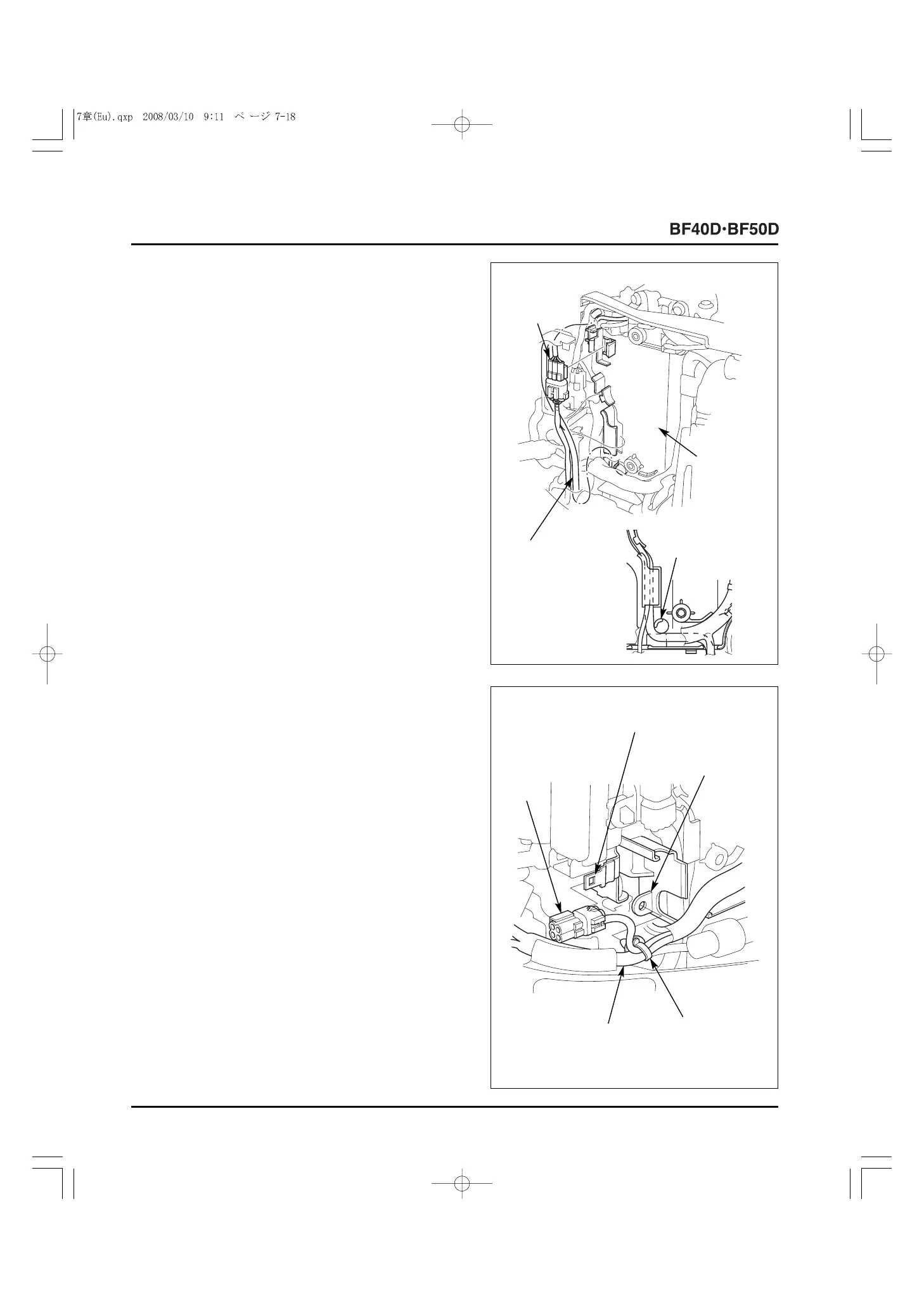
22) Set the alternator stator wire in each clamp on the electric
part case.
• Route the alternator stator wire under the round
projection in the position shown.
23) Install the trim angle sensor 3P connector on the electric
part case [Power trim/tilt type only].
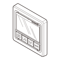
24) Install the main wire harness' harness band clip on the
electric part case.
25) Install the DLC (Data Link Connector) on the fuse box
bracket.
[3]
ALTERNATOR
STATOR WIRE
[2]
ELECTRIC
PART CASE
[4]
ROUND
PROJECTION
[3]
ELECTRIC
PART CASE
[2]
FUSE BOX BRACKET
[1]
DLC
[5]
MAIN WIRE
HARNESS
[4]
HARNESS
BAND CLIP
[1]
TRIM ANGLE
SENSOR 3P
CONNECTOR