14-61
1
2
3
4
5
6
7
8
9
10
11
12
13
14
15
16
17
18
19
20
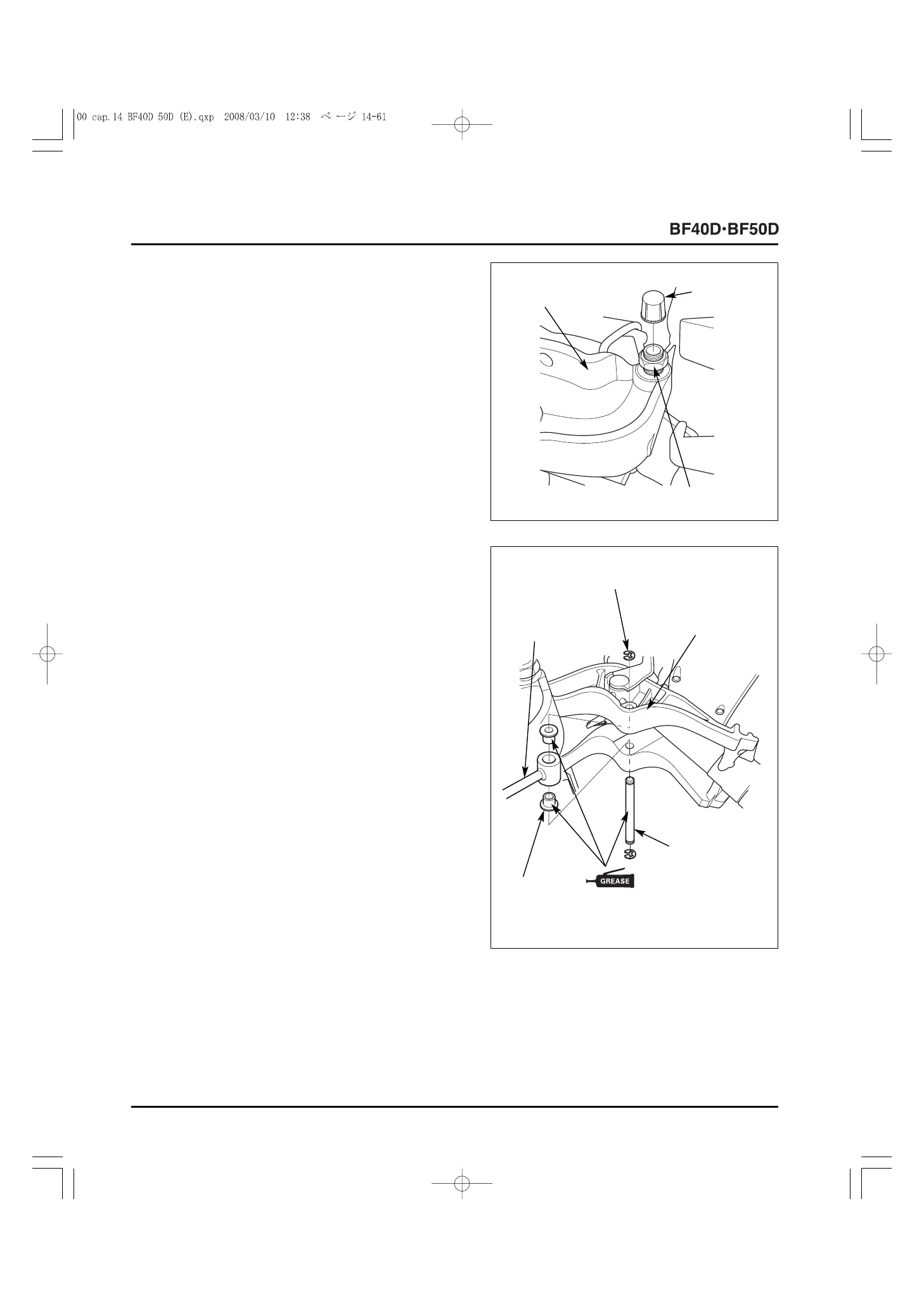
7) Holding the 7/8-14 UNF self-locking nut on the R. stern
bracket side, tighten the 7/8-14 UNF self-locking nut on the
L. stern bracket side to the specified torque.
TORQUE: 40 N
.
m (4.1 kgf
.
m, 30 lbf
.
ft)
8) After tightening to the specified torque, loosen the 7/8-14
UNF self-locking nut on the L. stern bracket side by
180
o
-
210
o
.
Apply rust-preventive agent to the threads of the tilting
shaft.
Install the tilting bolt cap.
9) When the upper cylinder bushings have been removed
from the gas assisted damper assembly, apply marine
grease to the outer surface of the new upper cylinder
bushings and install them on the piston rod.
Set the piston rod of the gas assisted damper assembly on
the swivel case assembly.
Apply marine grease to the outer surface of the upper
cylinder pin. Insert the upper cylinder pin into the swivel
case assembly and secure it with the 10 mm E-rings.
10) Lift up the outboard motor with a hoist and install it on the
boat.
11) When the outboard motor is locked with the tilt stopper,
move the tilt stopper to the "FREE" position.
Operate the tilt lever to lower the outboard motor to the
lowermost position, and move the tilt lever to the
"LOCK" position.
12) Install the following part.
- Engine cover (P. 4-2)
[3] 7/8-14 UNF SELF-
LOCKING NUT
[1]
L. STERN
BRACKET
[2]
10 mm E-RING (2)
[4]
UPPER CYLINDER
PIN
[6]
UPPER
CYLINDER
BUSHING (2)
[1]
PISTON ROD
[3]
SWIVEL CASE
ASSEMBLY
[2]
TILTING
BOLT CAP
[5]
(MARINE
GREASE)