15-9
1
2
3
4
5
6
7
8
9
10
11
12
13
14
15
16
17
18
19
20
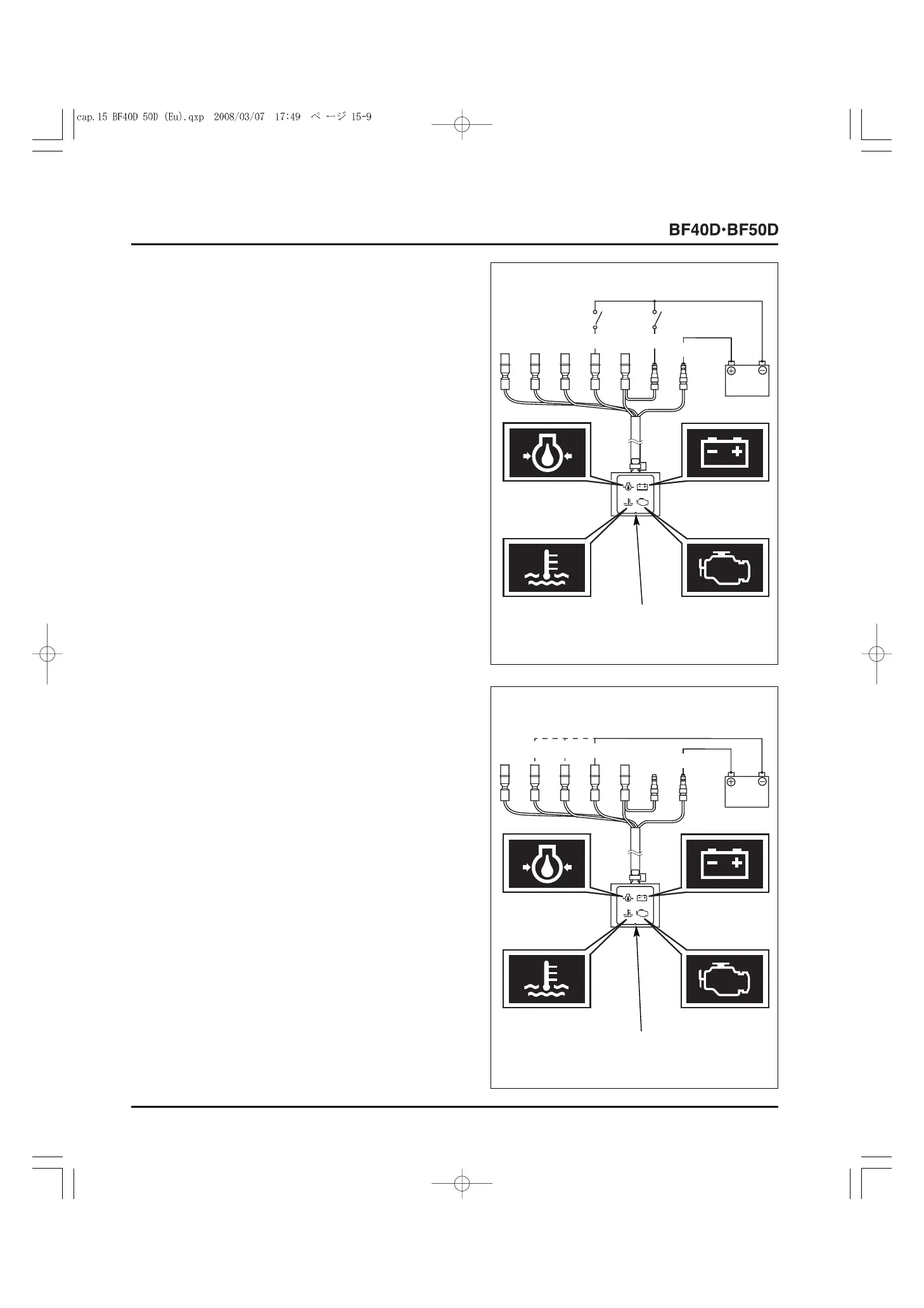
• INDICATOR LIGHT
• Use a known-good battery to check the indicator light.
1) Route the indicator light wires as shown. Connect the
switch 1 and the switch 2, which are connected to the
battery negative (
-
) cable, to the Black and Yellow
terminals.
Connect the battery positive (+) cable to the Black/Yellow
terminal and apply battery voltage (12V) to the terminal.
Check that the light 1 (Green light) comes ON when the
switch 1 is ON.
Check that the light 1 (Green light) goes OFF when the
switch 1 and the switch 2 are ON.
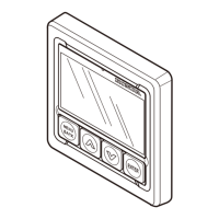
2) Connect the battery positive (+) cable to the indicator light
Black/Yellow terminal and the battery negative (
-
) cable to
the White/Blue terminal as shown. The light 2 (Red light)
should come ON.
3) Connect the battery positive (+) cable to the indicator light
Black/Yellow terminal and the battery negative (
-
) cable to
the Red terminal as shown. The light 3 (Red light) should
come ON.
4) Connect the battery positive (+) cable to the indicator light
Black/Yellow terminal and the battery negative (
-
) cable to
the Red/Blue terminal as shown. The light 4 (Red light)
should come ON.
5) If there is any abnormality, replace the indicator light with
a new one.
[3]
INDICATOR
LIGHT
[4] LIGHT 1
Y
Bl
Bl/Y
12V
[2] SWITCH 1
[1] SWITCH 2
[4]
INDICATOR
LIGHT
R/Bu
[1] LIGHT 1
[5] LIGHT 3
[2] LIGHT 2
[3] LIGHT 4
R W/Bu
Bl/Y
12V