19-2
1
2
3
4
5
6
7
8
9
10
11
12
13
14
15
16
17
18
20
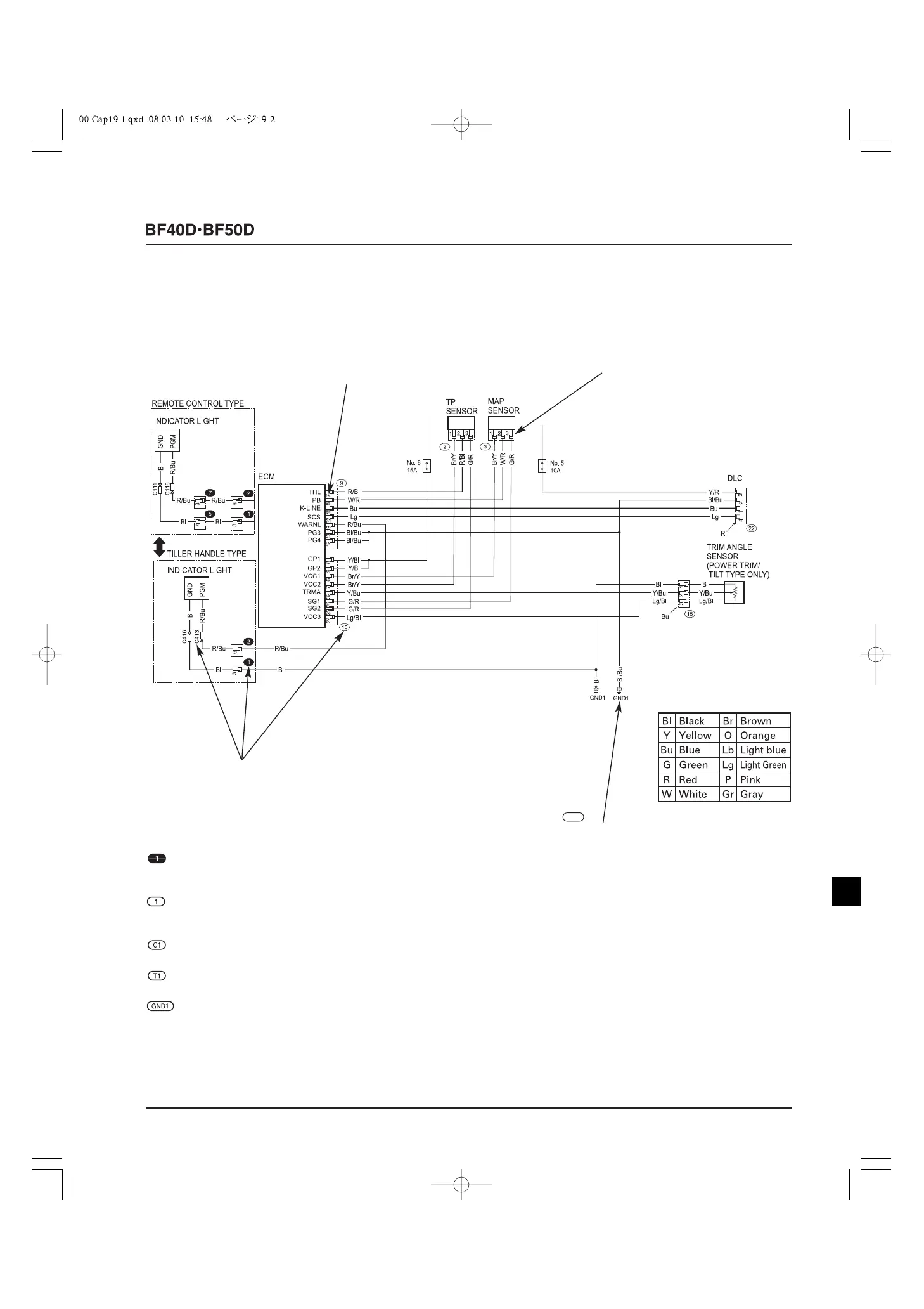
• HOW TO READ WIRING DIAGRAM
TERMINAL No.
SYMBOL OF TERMINAL
It shows the shape of each
terminal to identify whether it is
a male or female terminal.
GND1
Indicates the ground.
(Circled GND followed with
No. in white background)
CONNECTOR/TERMINAL No.
Every connector and terminal has a number to help the users find the
location and shape of the connector and the terminal arrangement by
referring to the "Connector general layout drawing" and/or the
"Connector drawing". All the connector/terminal numbers shown in
this Service Manual are either of those shown in this section.
: Connector that relays from a harness to a harness (Circled No. in
black background)
: Connector that connects to electrical equipment (Circled No. in
white background)
: Connector (Circled C followed with No. in white background)
: Terminal (Circled T followed with No. in white background)
: Ground (Circled GND followed with No. in white background)