EasyManua.ls Logo

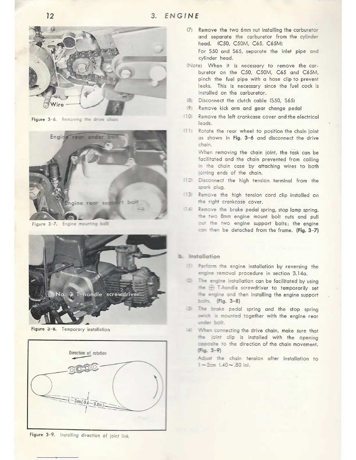
Honda C65 - Engine Installation; Engine Mounting Bolts View; Installing Direction of Joint Link; Temporary Installation View

Honda C65
127 pages
Print Icon
To Next Page IconTo Next Page
To Previous Page IconTo Previous Page
Loading...
72
Figure 3- 6.
Figure
:S
.- ti. Temporary installation
Fi9ure
3-9. I
ns
oil
in
g direction
of
joint link
3.
ENGINE
1
7)
Remove
the
two
6mm
nut ins
talling
the
carb
ure
and
separate
the
carburetor
from
the
c
ylinde-
head.
IC50,
C50M
,
C65
,
C65Ml
For
S50 and S65,
separate
the in
let
pipe
and
cylinde
r head.
!
Not
e)
When
it
is
necessary
to
remove
t
he
car-
bureto
r
on
the
C50,
C50M
,
C65
and
C65
M,
pinc
h the fuel
pipe
with
a hose
clip
to
pre
vent
leaks. This
is
necessary since
the
f
u~l
cock
is
in
stalled
on
the
carburetor.
9
0
Disconnect
the
clutch
cable
IS50, S65)
Re
move
kick
arm
and
§ear
change
pedal
Rem
ove
the
left
c
ra
nkcase
cover
and
the
e
le
ctrical
le
ads.
Rotate
the
rear
wheel
to
position
the
chain
joint
as shown in Fig.
3-6
and
disconnect
ihe
drive
chain.
Wh
en
removing
the chain joint, the ic]sk can
be
'acilit
a
te
d
and
the
chain
prevented
from
coiling
in
he
chain case
by
attaching
wires
to
both
·
oinin
g ends
of
the
chain.
Jisconn
ect
the
high
tension
.
terminal
from
the
soar
plug.
e
mov
e
the
high tension
cord
clip
installed
on
- e
right
crankcase
cove
r.
"erove
the
brake
pedal
spring,
stop
lamp spring,
--e
-wo
8m
m
engine
mount
bo
lt nuts
and
pull
- e
two
engine
support
bo
lt
s;
the engine
--
-. en be
detached
fr
om
the
fra
me. (Fig.
3-7)
-~---
- e en
gine
insta
llat
ion
by
revers
ing
the
;-;
-e
·e•oval
procedure
in
section
3.14a.
--;
e-;
·-
e
in
st
all
ation
can
be
facilita
t
ed
by
us
ing
;
::=:;
-
--a
die
sc
rewdr
i
ver
to
temporarily
set
-;
;-;;
--
e a d then installing the engine
support
g.
3-8}
ped
al
spring
and
the
stop
sp
r
ing
un
ed
together
wi
th
the
engine
r
ear
-e-
::~--ectin
g
the
dr
i
ve
chain, make sure
tha
t
::;·--
clip
is installed
with
the
opening
:::::::·-e
'o the
direct
ion
of
the chain
movement.
;:.
3-9
)
-:.
.s
·
'le
chain
te
n
sion
after
inst
allation
to
-
--
.40
--
.80
inL

Table of Contents