EasyManua.ls Logo

Honda C65 - Crankshaft Disassembly; Breather Functional Diagram

Honda C65
127 pages
Print Icon
To Next Page IconTo Next Page
To Previous Page IconTo Previous Page
Loading...
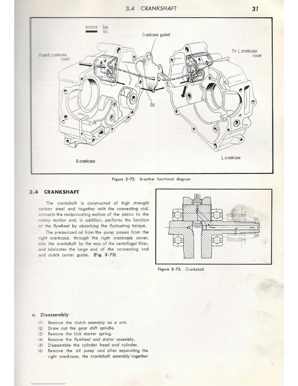
CRANK
S
HAFT
-
Cr
an
kcase
gasket
R
.crankcase
Figure
3- 72.
Breather
functional
diagram
3
.4
· CRANKSHAFT
The
cr
an
kshaft is
constructed
of high
st
rength
car
bon
steel
and
together
wi
th
the
connecting
rod,
con
ver
ts
the
reci
pro
cati
ng
motion
of
the
piston
to
the
rot
ary mo
ti
on
and,
in
addition,
performs
the
function
of
the
flywheel
by
ab
so
rbing
the
fluctuating
torque.
The pressu
riz
ed
o il
from
the pump passes
from
the
rig
ht
crankcase,
through
the
right
crankcase
cover,
in
to
the
cr
ankshaft
by
the
way
of
the
ce
ntrifugal
filter,
an
d
lubricates
the
l
arge
end
of
the
connecting
rod
an
d clutch
center
guide
. (Fig. 3-
73)
a .
Disassembly
(1 I Remove
the
clutch assembly as a unit.
(21
Draw
ou
t
the
gear
shift spindle.
(31 Remove
the
kick· st
arter
spring.
(41
Remove
the
flywheel
and
stator
assembly.
(51 Disassemble
the
cylinder
head
and
cy
linder.
(61 Remove the o
il
pump
and
after
separating
the
right
crankcase,
the
cranks
haf
t assembly
together
I
Figure
3-
73
. Crankshaft
31
To
L.cra
'
case
co
er
L
.c
rank
c
ase

Table of Contents