EasyManua.ls Logo

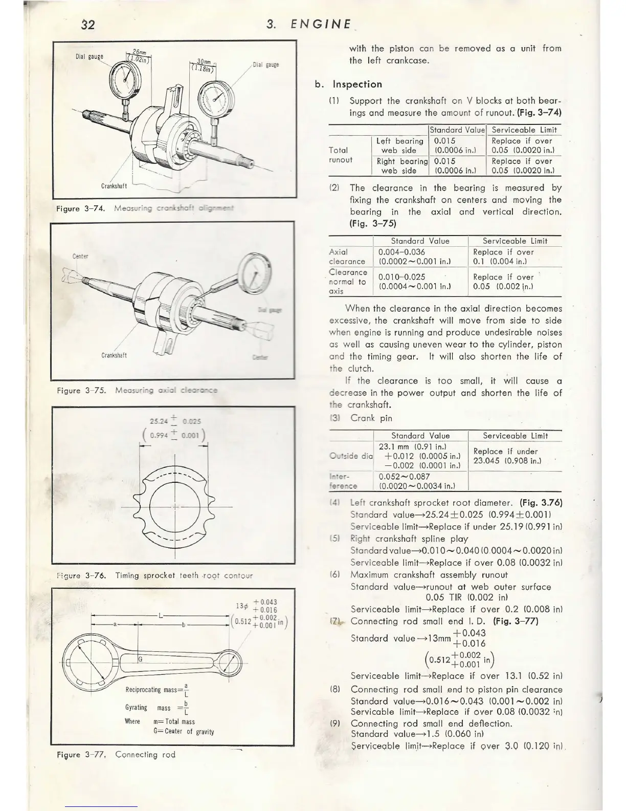
Honda C65 - Crankshaft Inspection; Measuring Crankshaft Alignment; Measuring Axial Clearances; Timing Sprocket Teeth Root Contour

Honda C65
127 pages
Print Icon
To Next Page IconTo Next Page
To Previous Page IconTo Previous Page
Loading...
32
3.
EN
Gl
N E
-
Figure
3- 74.
Measu
r•
g
c-r:-
,.,,.,__
0.:::
"'1
·
f/t=""'=
~
-
/
C
ra
nksh
aft
Figure
3- 75.
Meas
,·
g
C>t:O
=
=-=-=-==
Fig
u
re
3-
76
. Timing
sprocket
teeth -
ro
9t
co
n
our
13¢
+0.04
3
+ 0.016
1--
-
----
L
-----
- (
0512
+o.oo2
.)
-~
--
-
-
---
- · +0.001
1
"
G
Rec
ipro
c
atin
g
mas
s=
-[
b
Gy
rat
ing
ma
ss = L
W
her
e m= Total mass
G=
Ce•ter
of
g
ravity
fi9ure
3-
77
,
Connec
tin9
rod
with
the
piston con be removed as a unit
from
the
left
crankcase.
b .
Inspection
11
I Suppo
rt
the crankshaft
on
V blocks
at
bo
th
bear-
ings and measure the amount of runout. (Fig. 3- 7
4)
Standard Value Servi
ceab
le
limit
L
eft
bearing
0.015
Rep
la
ce
if
ove
r
To
tal
web
si
de 10.0006 i
n.)
0.
05
10.0020 in.)
r
unout
Right b
earing
0.015
Replace
if
over
web
side
10.0006 in
.l
0.
05
10.0020
in.l
1
21
The
clearance
in the
bearing
is measured
by
fixing the cranks
haft
on
centers
and
moving
the
bearing
in the
axial
and
vertical
direction
.
(Fig. 3-
75)
Standard Value
Se
r
viceab
le
limit
Axi
al
0.004-0.036
Replace
if
over
clearance
10
.
0002~0.001
in.) 0.1 10.004 in.l
Clea
rance
0.010- 0.025 Replace if
over
no
rmal to
axis
10.0004~0. 00
1
in.l
0.05 10.002 [n.l
W hen
the
clearance
in the axial
direction
becomes
excessive, the cranks
haft
wi
ll move
from
side
to
si
de
when engine
is
running and
produ
ce undesirable noises
as
wel
l
as
causing
un
even
wear
to
the cylinder, piston
and
the timing
gear.
It
will
also sh
orten
the
lif
e
of
he clutch.
If
the
clearance
is
too
sma
ll,
it
.;,.i
ll cause a
decre
as
e in
the
power
output
and
shorten
the
life
of
he cranks
haft
.
'31
Cron
k pin
0 ·
sd
e
dia
Stan
dard
Value
23.1
mm
10.91
in.)
+0.012
10.0005
in.l
-0
.002
10
.0001 in.l
0
.052~0
.
087
1
0.0020~0
.
0034
in.)
Serviceab
le
limit
Replace
if
und
er
23.045
10.908
in.l
t
lef
t crankshaft
sp
ro
cket
root
diameter. (Fig. 3.76)
S
ond
ard
vo\ue-+25
.
24±0
.
025
(0.994±0.0011
Servic
eab
le Jimit
-+
Replace
if
under 25.1910.991 in)
1
51
Right crankshaft
sp
li
ne
ploy
Stand
ard
vo
lu
e-+0.0
1
0-0.040
(0
0004-0
.
0020
in!
Ser
vic
eable
\i
mit
-+
Reploce
if
over
0.08
10
.
0032
in)
161 M ax
imum
cranks
haft
assembly r
un
out
S
tandard
vo
lu
e
-+
runout
at
web
outer
surface
0.05
TIR
10
.002
in!
Servic
eable
limit->Reploce
if
ove
r
0.2
(0.008 in)
IZ
J,.
Connecting
rod
sma
ll end
I.
D. (Fig.
3-77)
+0
.
043
Standa
rd
volu
e-+
13mm+0
.0
16
(0
512
+0.002.
)
· + 0.001
rn
S
erviceab
le limit
-+
Rep
loce
if
over
1 3.1 10.52 inl
181
Connecting
rod
sma
ll .end
to
piston pin
clearance
Standard vo\ue-+0.01
6-0
.
043
(0.001
-0
.
002
in)
Servicoble
limit
-+
Reploce if
over
0.08
10.0032
;n)
191
Connecting
r
od
sma
ll end
deflection.
Standard va
lu
e-+
1 .5 (0.060 in)
S
ervi
c
eab
le limit
-+
Reploce
if
o
ver
3.0
(Q.
120
i
n)

Table of Contents