EasyManua.ls Logo

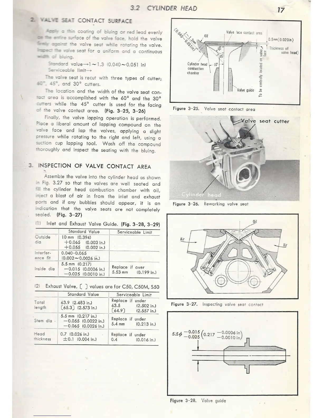
Honda C65 - Exhaust Valve, Values Are for C50, C50 M, S50; Inlet and Exhaust Valve Guide Table; Inspection of Valve Contact Area; Valve Seat Contact Surface

Honda C65
127 pages
Print Icon
To Next Page IconTo Next Page
To Previous Page IconTo Previous Page
Loading...
c
CO
TAO
;~g
c· :: _
-;;
:: ·
·e::
eaa
ev
e
nly
e
.::
e =::::e
-::
o
1h
e va
lv
e
o
lv
e seo· -- e
·:::·c·
-~g
the valve.
--=
::
e
seoi
ior
a
.__--=:::--
o-d
a
co
ntinuous
= - -.g.
·::-a
valu
e--->
I
~
1.3
1
0.040
~0.05
1
inl
- :: re s
eat
is recut
with
three
types
of
cu
tter;
-::=
and
30°
cutt
er
s.
--,
oca
i
on
and the
wid
th
of
the
valve
seat
con
-
==-
::-·eo is accomplished
wit
h the
60°
and
the
30°
·
=-
-e-s
whil
e the 45°
cutter
is
used
for
the
facing
::=
·-:e va
lv
e
contact
area.
(Fig. 3-
25,
3- 26)
=;
nolly,
the
va
lve
lopping
operation
is
performed.
= a::e a
lib
eral amount
of
lop
ping
compound
on
the
:::
e f
ace
and
lop
the valves,
applying
a slight
::·essure
while
rotating
to
the right and
left,
using a
=-..::-ion cup
lopping
too
l.
Wash
off
the compound
·•oroug
hly and inspect the seating with the bluing .
• I
SP
ECTION
OF
VALVE
CONTACT
AREA
Assemble the
valve
into
the
cylinder
head as shown
- Fig. 3.
27
so th
at
the
valve
s
ore
we
ll seated and
.-
he
cy
linder
head
combustion chamber
with
oil,
-
--ect
a
bla
st
of
air
in
fr
om
the
inlet
and
exhau
st
:>or s and
if
any
bubbles should
appear,
it
is
on
--
dicot
ion
that
the volye seats
ore
not
comp
letely
sealed. (Fig. 3- 27)
In
let
and Exhaust -
Valve
Guide.
(Fig. 3- 28, 3- 29)
Standard
Value
Servi
ceab
le
Limit
Outsi
de
10
mm
10
.394)
d"
a
+0.065
10.003 in.l
+0.05
5
10.002
in.l
~t
erfer-
0.040
-
0.065
ence
fit
1o
.
oo2-o
.
oo26
in
.)
5.5
mm
10.
2 17)
Repla
ce
if
over
•side
dia
-
0-015
10.0006 in.)
-0.025
10.0010 in.l
5.53
mm
10
.
199
in
.)
21
Exhaust Va
lv
e, [ J values
ore
for
C50
, C50M, S50
St
andard
Va
lu
e
Serv
i
ce
abl
e
Limit
Total
63
.9
12
.
483
in
.)
Repl
ace
if
und
er
en
gth
(
65
.3)
12.573 in.)
63.5
12
.
502
in.l
(
64.9)
12.557 in.l
5.5
mm
10.217 in.)
Replace
if
under
•em
dia
-
0.055
10.00
22
in.)
-
0.065
10.00
26
in.l
5.4
mm
<0.213 in.l
ead
0.7
10.026 in.l
Replace
if
under
··
ic ness
± 0.1
10
.
004
in.l
0.4
10.016 in.l
DER
H
EAD
17
V/
al
ve
f
ac
e
co
ntact
;:~~z
~
~~~~~
~~::;=·
0.
5
0.0
20in
~
Cylinder
head
combu
s
tion
chamber
Figure
3- 25.
Valve
seat
contact
area
Figure
3-
26
. Reworking valve
seat
1
'1
HiC· ·ess
of
1;:
~
valve
head
)
:;~
~
0
'0
~
~
0
seat
cutter
Fi
g
ur
e 3-
27
.
In
s
pe
ct
ing val
ve
seal
contact
5
.
5
rfi
- 0.
015
(a
2
17
-o
.
ooo6
in)
. -
0.025
.
-0.0010in
Fieure
3-
28.
Val
ve
euide

Table of Contents