EasyManua.ls Logo

Honda C65 - Suspension System Maintenance

Honda C65
127 pages
Print Icon
To Next Page IconTo Next Page
To Previous Page IconTo Previous Page
Loading...
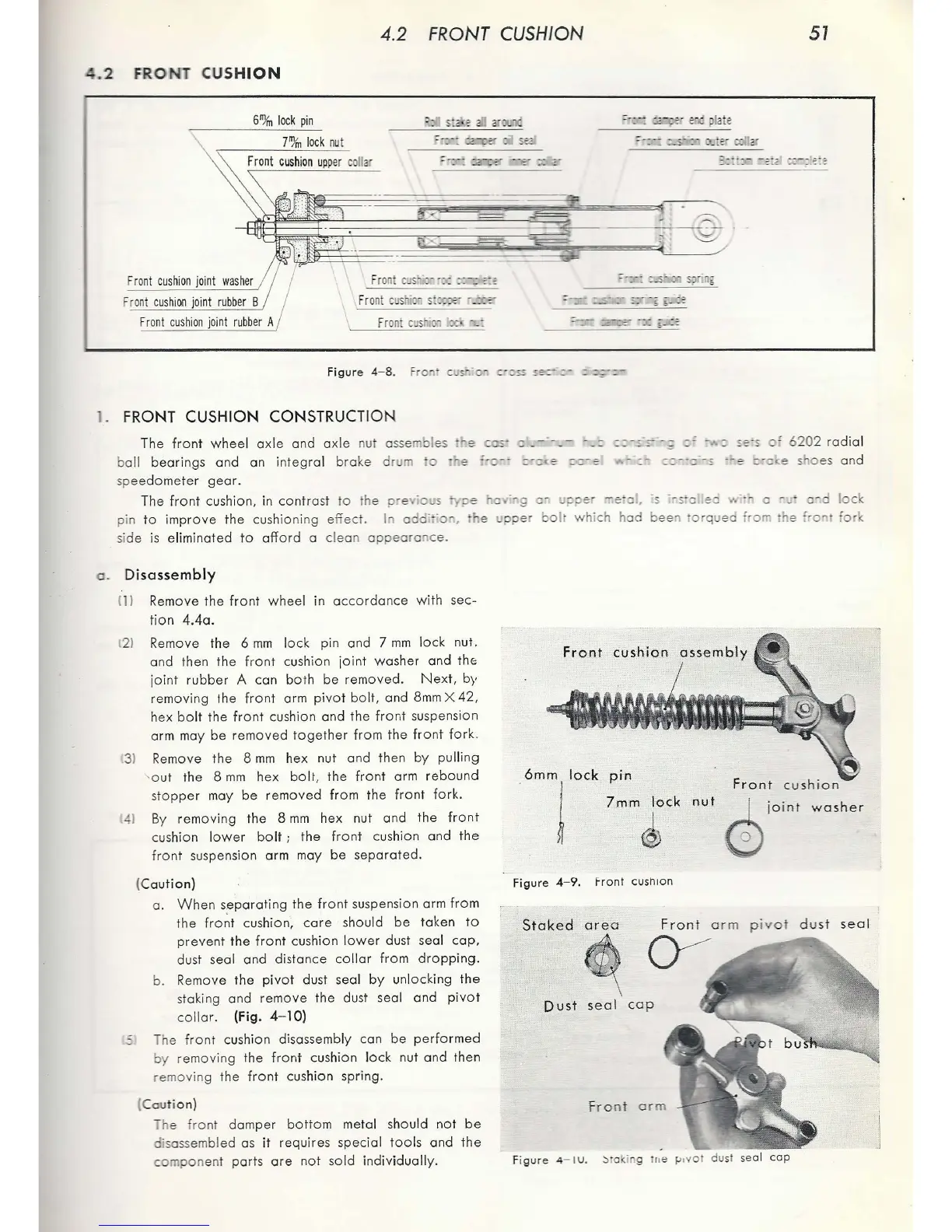
4.2
FRONT
CUSHION
51
.2
FRONT
CUSHION
6"Ym
lock
pin
Figure 4
-8.
Fron c
~
-
c:-::ss
s=-
~-
_
1. FRONT CUSHION CONSTRUCTION
The
front
whee
l a
xle
and
axle
nut assembles e
cas-
:: _- ·- - -
---
- - - -
::=
-,::;
:e
·s
o'
620
2
rad
ia l
ball
bearings
and
an
inte
gr
al
bra
ke
drum
o
·
~>e
:--::::
-·
::·:: e
::-e
·
::-
:::::-·::·
-s
·· e
::·c
e sho
es
and
sp
ee
dometer
gear
.
The
front
cushion, in
contras
t
to
the
pr
e io s
pe
a.
··
~g
a-
uppe
eia
l,
·s
;
-s'o
.
eo
.·.
·.;. o -
~
-
a~d
l
oc
pi
n
to
improve
the
cushioning e
ffect.
In
odd
cii
o-
,
he
upp
er
bo
l
wh
ich
hod
be
en
·or
quea
from
e
f•on:
'or
si
de
is
eliminated
to
afford
a
clea
n
appe
ar
ance.
o.
Disassembly
11
I Remove the
fr
on
t
wheel
in
acc
o
rdance
with sec-
tion
4.4a.
121 Remove the 6
mm
l
oc
k pin
and
7
mm
loc
k nut.
and then
the
front
cushion
ioint
washer
and
the
io
int
rubber
A can
both
be
rem
oved
.
Next,
by
removing the f
ront
arm pi
vot
bolt,
and 8mm X
42,
hex
bo
ll
the
front
cushion
and
the
front
suspension
ar
m may
be
re
moved
together
fr
om
the
front
fork.
t
31
1
41
Remove the 8
mm
hex nut a
nd
then
by
pulling
' o
ut
the
8
mm
hex
bo
l
t,
the
f
ron
t
arm
r
ebo
und
stoppe
r may
be
removed
from
the
front
fork
.
By
removing
the
8
mm
hex
nu
t
and
the
front
cushion
lower
bolt
;
the
front
cushion
and
the
fron
t suspension arm may
be
separa
ted.
{
Cautio
n)
a.
When
separating
the
front
suspensi
on
arm
fro
m
the
fr
o~
t
cushi
on,
core
sho u
ld
be
taken
to
prevent
the
front
cushion
lowe
r dust seal
cap,
dust s
eal
and
distance
co
llar
from
dropping.
b. Remove
the
pivot
dust seal by
unlock
ing
the
stak
ing
and
remove
th
e dust seal
and
pivot
co
lla
r.
{Fig.
4-10)
The
front
c
ush
ion
dis
ass
embly can
be
performed
by
removing
the fr
ont
cushion
lo
ck nut and then
re
mov
ing
the
front
cushion spring.
(Ca
uti
on)
The
fr
o nt
damper
bottom
metal
sh
o
uld
not
be
di
sass
emb
led
as
it
requires
specia
l
tools
and
the
com
po
nent
parts
a
re
not
sold
indiv
iduall
y.
pin
7mm
l
ock
nut
~
Figure
4-9
. f ront cushi
on
Staked
area
~
ar
m p i
vo
t d u
st
s
ea
l
D
ust
s
ea
I
cap
Fr o
nt
ar
m
Figure
4
-I
U. ::. oking ue
fJovof
du
st se
al
c
ap

Table of Contents