USER GUIDE FALCON
93 EN2Z-0962GE51 R0715
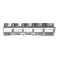
I/O Pull-up Resistor Handling
The following diagram and table shows the pull-up resistor handling when using XFL
und XFC modules with the Excel Web controller.
A
D
18.2 kOhm
(pull-up)
100 k
Ù
100 kOhm
5 V
A
D
24.9 kOhm
(pull-up)
150 k
Ù
49.9 kOhm
10 V
Case 1 Case 2
Fig. 15. Input circuit diagram
Table 1. Pull-up resistor handling
device
input
circuit
diagram
(Fig. 15)
voltage hardware
Can be
deactivated
(1)
by DIP
switch
configured
by plug-in
activated
for DI on
AI
(2)
with NTC
or low-
impedance
input
input or
high-
impedance
XFL521A/B 10 V
optional
switch-off
YES NO YES YES
case 1 8.89 V
0 V
5 V case 3 5 V
(1
by using CARE ≥ 7.01, by selecting I/O characteristic "No Pull-up" in the analog input datapoint.
(2
automatically by using CARE ≥ 7.01
I/O Initializiation
Input Datapoints (AI, BI)
Start BACnet input datapoints will be initialized with the value ´zero`. After initialization,
the field devices values will be read. If no value is received after the set heartbeat
time (default = 60 s), the Excel Web controller polls the input module.
Alarm behavior At the beginning, all input points are not in alarm by default except those of which
input values have caused an alarm.
After the start alarm time has expired, an alarm will be saved in the alarm buffer,
shown in the alarm list and reported to the EBI as long as the alarm exists.
Restart, Reset, Power Failure,
Application- and Firmware Download
The following values/statuses will always be saved in the battery retentive RAM and
restored after restart, reset or power failure of the Excel Web controller.
• Runtime counter
• Last reset time
• Elapsed active time
• Out of Service flag
• Points in manual operating mode
The advantage here is that these values will survive an application and
firmware download.
When an Excel Web controller is replaced, these values cannot be transferred
to the new Excel Web controller.
 Loading...