S3 Series UL Listing Document — P/N LS10005-051GF-E:D3 3/09/2016 25
Municipal Box Connection Installation Wiring
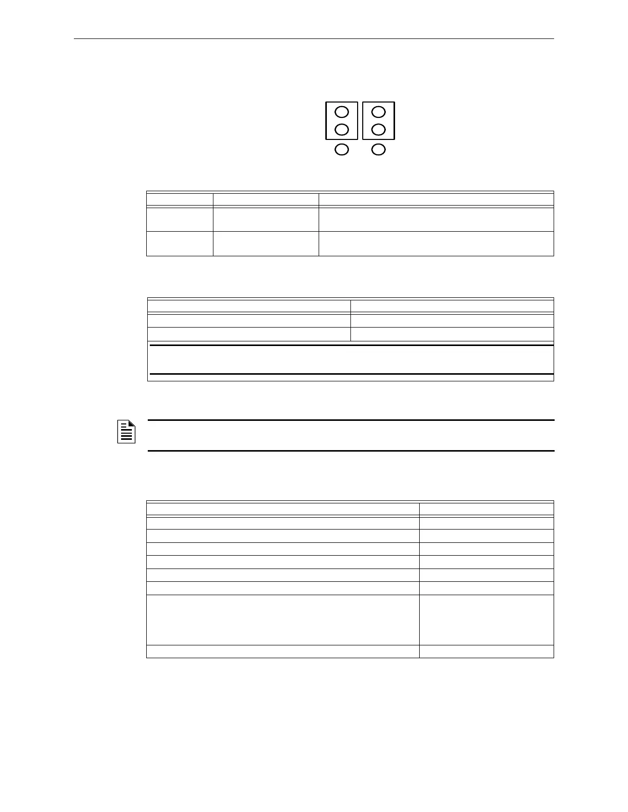
2.8.1 W1 Jumper Block (Polarity Reversal Configuration)
Figure 2.8.1.1 illustrates the W1 jumper block positions for the polarity reversal configuration.
Figure 2.8.1.1 W1 Jumper Block Positions for Polarity Reversal
Table 2.8.1.1 lists the Reverse Polarity communication line circuits.
2.8.2 Reverse Polarity Circuit Specifications
Table 2.8.2.1 lists the reverse polarity circuit specifications.
2.8.2.1 Remote Station Receiving Unit Disclaimer
2.9 Municipal Box Connection
For information on the terminal connections of the Municipal Box Connection Specifications, refer to
Table 2.9.1. For information on the W1 Jumper, refer to Figure 2.9.1.1.
Designation Description Comments
TB2-5 MUNI + Positive Output to Local Energy City Box, Remote Station
or Releasing Solenoid (See Figure 2.8.1.1).
TB2-6 MUNI - Negative Output to Local Energy City Box, Remote
Station or Releasing Solenoid (See Figure 2.1.1.1).
Table 2.8.1.1 Reverse Polarity Circuit-Installation Wiring Terminals
Requirements Reverse Polarity Specifications
Circuit supervision Not Supervised
Max. voltage, rated current, and frequency 24 VDC, 0.012 amps
NOTE: Supervision of a polarity reversal circuit is performed by the Remote Station Receiving
Unit, not the fire alarm control panel.
Table 2.8.2.1 Reverse Polarity Specifications
DISCLAIMER: Intended for connection to a polarity reversal circuit of a remote station receiving
unit having compatible ratings.
Requirements Municipal Box Specifications
Circuit supervision: Supervised
Circuit Power Requirements: Non Power-Limited
Type of connection, series (local energy) or shunt: Local Energy (TB3-8 and TB3-9)
Trip coil resistance value: 14.5 ohms
Trip current: 0.51 amps
Max. voltage frequency: 24 VDC
Is a shunt connection or a local energy connection pertain to the terminals.
If a shunt connection is indicated, add the following next to the terminals:
The shunt connection is recognized only as a supplementary signaling unit
as part of a local control unit and is not recognized as an auxiliary control
unit connection per NFPA 72.
Local Energy connection
Impedance values for testing at which ground faults are annunciated. Zero Ohms
Table 2.9.1 Municipal Box Connection Specifications

 Loading...


