S3 Series UL Listing Document — P/N LS10005-051GF-E:D3 3/09/2016 45
S3 Series System Operation Operation
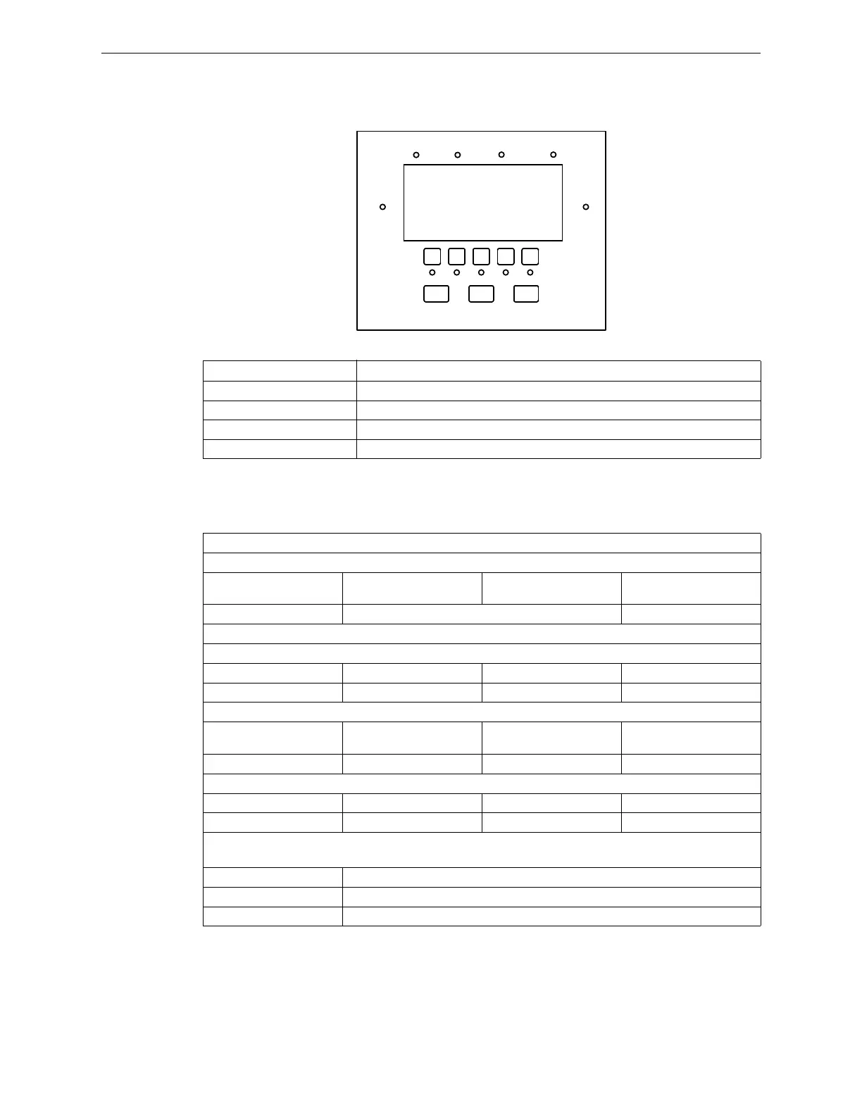
3.1.4 LCD-SLP Switches
Figure 3.1.4.1 illustrates the LCD-SLP switches. Table 3.1.4.1 lists the LCD-SLP switches and a description.
Figure 3.1.4.1 LCD-SLP Switches
3.2 S3 Series System Operation
Table 3.2.1 lists the S3 Series System operation.
3.3 Operating Instructions
Frame and mount the S3 Series Operating Instructions (Part Number: LS10056-000GF-E), adjacent to the S3
Series (Small Addressable Fire Alarm Control Panel).
Designation Description
Menu Toggles the Menu ON and OFF.
Drill Initiates a fire drill.
Reset Initiates a System Reset, as well as five User-Defined switches.
User Defined Switches Custom indication and switch function, must program in CAMWorks.
Table 3.1.4.1 Switches
FIRE ALARM HAZARD SUPERVISORY TROUBLE
AC POWER SILENCED
MENU DRILL RESET
System Types
Local:
Emergency relocation
(paging)
Live Pre-Recorded
Emergency communication (telephone)
Local with Shunt:
Protected premise Unit:
Auxiliary Proprietary SIA CP-01-2000
Central Station Remote station
Supervising Station Unit:
Auxiliary (Public Fire Alarm
Reporting System)
Proprietary
Central Station Remote Station
Communication Transmission Path:
Coded Reverse Polarity
Non-Coded
Releasing
Cross Zone, Counting Zone and NFPA 13, Sprinkler Systems
Cross Zone
Counting Zone
NFPA 13, Sprinkler Systems
Table 3.2.1 S3 Series System Operation

 Loading...


