S3 Series UL Listing Document — P/N LS10005-051GF-E:D3 3/09/2016 11
SLP-E3 Main Circuit Installation Wiring Diagram Installation Wiring
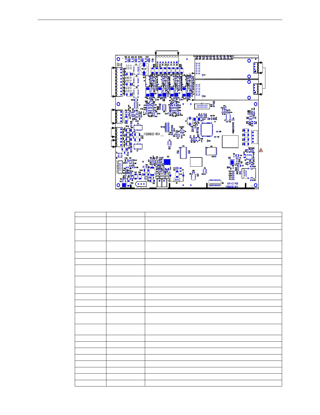
2.2 SLP-E3 Main Circuit Installation Wiring Diagram
The S3 Series System uses the SLP-E3 main board as the main circuit board. Figure 2.2.1 shows the SLP-E3
main circuit board sub-assembly.
Figure 2.2.1 SLP-E3 Main Circuit Board
2.2.1 SLP-E3 Main Circuit Board Installation Wiring Terminals
Table 2.2.1.1 lists the SLP-E3 main board installation wiring terminals.
SLP-E3
SLC-PM/SLC95-PM #2
SLC-PM/SLC95-PM #1
TB4
TB3
TB2
TB1
TB5
BAR CODE
LABEL
PRODUCT
SERIAL NUMBER
PRODUCT
DATE CODE
LABEL
ETHERNET
J2
W1
J7
J3
JTAG
TB1
TB1
W3
TB6
BAT+ BAT-
J1
J4
SW5 SW4
SW3 SW2
MUNICIPAL/
RELEASING CIRCUIT
NON-POWER-LIMITED/
POLARITY REVERSAL
CLASS 2
POWER-LIMITED
RS-485 BUS
INTERFACE
FORM “C” DRY
CONTACTS
NAC CIRCUITS
SLC
CIRCUITS
FOR SYSTEM
SENSOR
(SLC-PM)
OR
APOLLO
(SLC95-PM)
DEVICES.
(SEE NOTE 1)
RS232 INTERFACE
NETWORK
NOTE 1:
DO NOT
COMBINE
SLC-PM WITH
SLC95-PM.
- IF SYSTEM
SENSOR, USE
SLC-PM.
- IF APOLLO,
USE SLC95-PM.
B- B+
SW1
AUXILIARY POWER
WARNING!
INSTALLTHE
SLC-PM/
SLC95-PM
COMPONENT
SIDE UP!
J5
J6 J1
J1
(SEE WARNING).
(SEE WARNING).
Designation Description Comments
TB1-1 NAC 1 B+ Notification Appliance Circuit 1, B+
TB1-2 NAC 1 B- Notification Appliance Circuit,1 B-
TB1-3 NAC 1 A+/NAC 3 B+Notification Appliance Circuit 1, Class A+ RETURN or Notification
Appliance Circuit 3 B+
TB1-4 NAC 1 A-/NAC 3 B- Notification Appliance Circuit 1, Class A- RETURN or Notification
Appliance Circuit 3 B-
TB1-5 NAC 2 B+ Notification Appliance Circuit 2 B+
TB1-6 NAC 2 B- Notification Appliance Circuit 2 B-
TB1-7 NAC 2 A+/NAC 4 B+Notification Appliance Circuit 2 Class A RETURN A+ or Notification
Appliance Circuit 4 B+
TB1-8 NAC 2 A-/NAC 4 B- Notification Appliance Circuit 2 Class A RETURN A- or Notification
Appliance Circuit 4 B-
TB2-1 RESET B+ Resettable 24 VDC Auxiliary Power
TB2-2 GND Resettable or Non-Resettable Power Common Negative
TB2-3 AUX B+ Non-resettable 24 VDC Auxiliary Power
TB2-4 Make no connection
TB2-5 MUNI + Positive Output to Local Energy City Box, Remote Station or Releasing
Solenoid (See Note 1 and Jumper W1).
TB2-6 MUNI - Negative Output to Local Energy City Box, Remote Station or Releasing
Solenoid (See Note 1 and Jumper W1).
TB3-1 RS-485 Interface AUX RS-485 COMM A Output
TB3-2 RS-485 Interface AUX RS-485 COMM B Output
TB3-3 Ground Earth Ground
TB3-4 Reserved Spare (N/C)
TB4-1 ALRM NC Alarm relay contact normally CLOSED N/C
TB4-2 ALRM NO Alarm relay contact normally OPEN N/O
TB4-3 ALRM C Alarm relay contact common
TB4-4 SUPV NC Supervisory relay contact normally CLOSED N/C
Table 2.2.1.1 SLP-E3 Main Circuit Board Installation Wiring Terminals

 Loading...


