34 S3 Series UL Listing Document — P/N LS10005-051GF-E:D3 3/09/2016
Installation Wiring S3 Series System, SLP-BB Cabinet Assembly
2.14 S3 Series System, SLP-BB Cabinet Assembly
The SLP-BB (Smart Loop Panel-Backbox) (Part Number: SLP-BB) assembly typically houses the following
units:
• Backbox
• Outer Door
– LCD-SLP Display Panel
– Door Insert
• Hardware Kit
2.14.1 SLP-BB Cabinet Installation
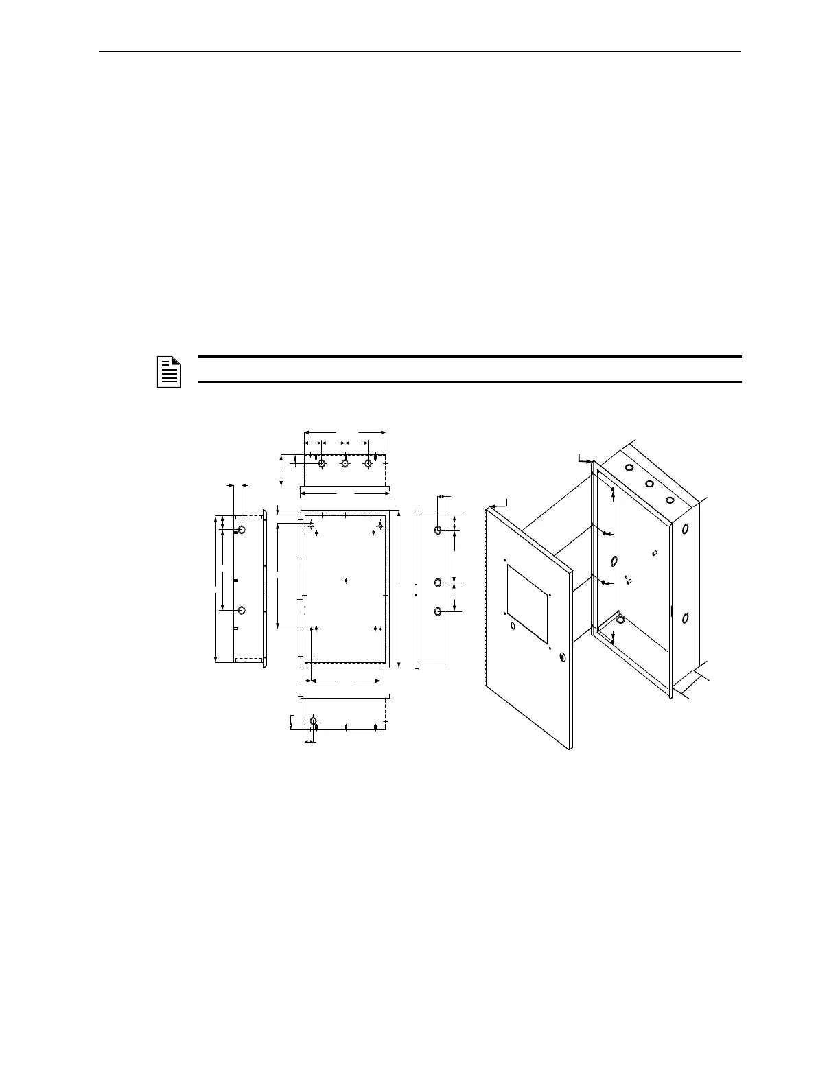
Figure 2.14.1.1 illustrates the SLP-BB cabinet dimensions.
Figure 2.14.1.2 illustrates the SLP-BB outer door and backbox installation.
To install the SLP-BB outer door to the backbox, refer to the following.
1. To mount the SLP-BB outer door to the backbox, insert four nuts (#6 Hex Kep) in the four-hole mounting
pattern and secure the nuts from the outer door to the left side of the backbox as shown in Locations 1, 2,
3 and 4 of Figure 2.14.1.2.
– SLP Main Board – FLSP-7 Power Supply – RPT-E3-UTP (Optional)
– SLC-PM/SLC95-PM – Batteries – DACT-E3 (Optional)
NOTE: Use the Hardware Kit provided with the SLP-BB Cabinet assembly.
Figure 2.14.1.1 SLP-BB Cabinet
Dimensions
Figure 2.14.1.2 SLP-BB Outer Door to
Backbox Assembly
0.80"
14.45/64"
1.3/32"
12.00"
20.1/8"
1.25"
11.00"
2.00"
1.25
"
1.3/32"
14 1/2"
4.00"
4.00"
3.3/ 64"
4 1/2"
1.25"
15.1/2"
21 1/2"
1
2
34
3 29/32"
7 3/32"
2"
1 ¼”
1
2
3
4
1
4
1
/
2
"
W
20 1/8"H
4 1/2" D
SLP-BB CABINET
OUTER DOOR
SLP-BB CABINET
BACKBOX

 Loading...


