S3 Series UL Listing Document — P/N LS10005-051GF-E:D3 3/09/2016 21
Remote Annunciator/Keypad Circuits Installation Wiring
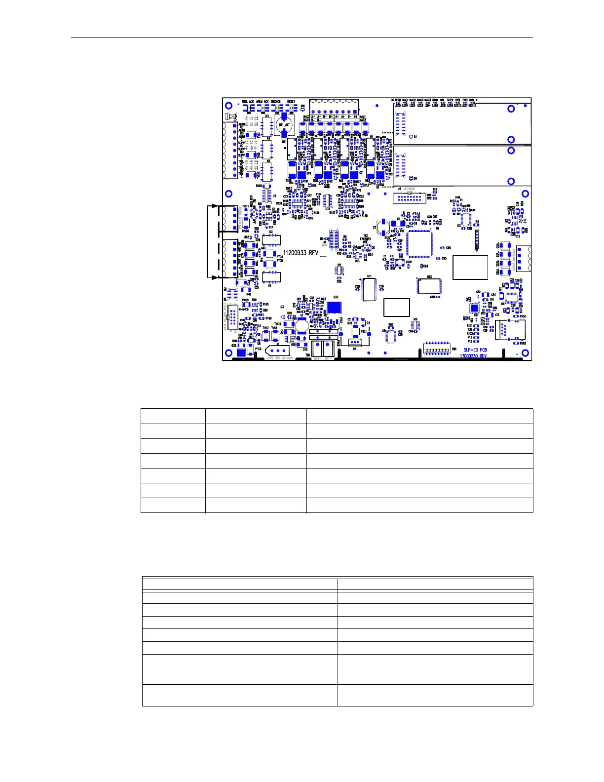
2.7.7 Remote Annunciator Installation Wiring Diagram
In the S3 Series System, the Liquid Crystal Display-Smart Loop Panel (LCD-SLP) is the Local Annuncia-
tor/Keypad Circuit for the SLP. Figure 2.7.7.1 illustrates the remote annunciators on the SLP main board
panel.
Figure 2.7.7.1 Remote Annunciator Installation Wiring Diagram
2.7.8 Remote Annunciator Installation Wiring Terminals
Table 2.7.8.1 lists the S3 Series, Remote Annunciator installation wiring terminals.
2.7.9 Remote Annunciator Specifications
Table 2.7.9.1 lists the specifications for the following remote annunciators connected to the SLP-E3 panel.
SLP-E3
SLC-PM/SLC95-PM #2
SLC-PM/SLC95-PM #1
TB4
TB3
TB2
TB1
TB5
BAR CODE
LABEL
PRODUCT
SERIAL NUMBER
PRODUCT
DATE CODE
LABEL
ETHERNET
J2
REMOTE
ANNUNCIATORS
W1
J7
B- B+
J1
J5
J6
J1
Designation Description Comments
TB2-1 RESET B+ Resettable 24 VDC Auxiliary Power
TB2-2 GND Resettable Power Common Negative
TB2-3 AUX B+ Non-Resettable +24 VDC Auxiliary Power
TB2-4 NC Make No Connection
TB3-1 RS485 Interface Aux RS485 COMM A Output
TB3-2 RS485 Interface Aux RS485 COMM B Output
Table 2.7.8.1 S3 Series, Remote Annunciator Installation Wiring Terminals
• ANU-48 • ASM-16 • LCD-7100 • RAN-7100 • LCD-SLP • LCD-E3
Requirements Remote Annunciator Specifications
Circuit Supervision: Supervised
If the circuit is power-limited: Class 2 Power-Limited
Maximum voltage, rated current: 0.150 amp (maximum)
Maximum line voltage: 24 VDC
Maximum line impedance for Remote Annunciators: 120 Ohms
Identify the Manufacturer’s Name, Model designation
for appliances to be used on the circuit or reference the
device compatibility section/document.
Devices hook to RS-485 for the following models: LCD-
7100, LCD-E3, LCD-SLP, ASM-16 and ANU-48.
Impedance values for testing at which ground faults are
annunciated.
Zero Ohms
Table 2.7.9.1 Remote Annunciator Specifications

 Loading...


