S3 Series UL Listing Document — P/N LS10005-051GF-E:D3 3/09/2016 43
S3 Series System Configuration Installation Wiring
2.20 S3 Series System Configuration
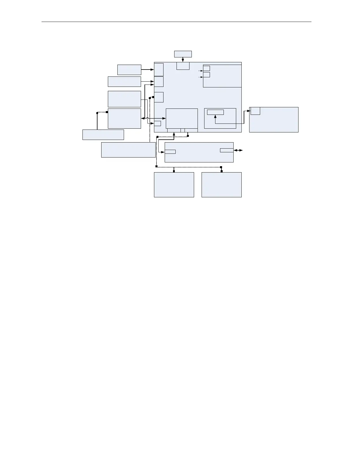
Figure 2.20.1 illustrates an overview of the S3 Series System configuration.
Figure 2.20.1 S3 Series System Configuration
SLP-E3
MAIN BOARD
LCD-SLP
connects to
Local Display
DACT-E3
connects to
Central Station
RPT-E3-UTP
Connects to
another RPT-E3-UTP,
SLP-E3 or E3 Panel
FLPS-7
7 amp Power Supply
SLC-PM or
SLC95-PM
connects to
SLC Devices
(See Note 1)
J4
J10
SLP-E3 Overview Diagram
J7
NACs
Plug-in
BATTERIES BATTERIES
AC INPUT
NON-POWER-LIMITED
NOTE 1:
YOU CANNOT COMBINE SLC-PM
WITH SLC95-PM.
- IF SYSTEM SENSOR, USE SLC-PM.
- IF APOLLO, USE SCL95-PM.
BATTERY WIRE
TB1
DACT-E3 WIRING:
NON-POWER-LIMITED
MUNICIPAL CIRCUIT LOCAL:
Energy Masterbox, Releasing,
NON-POWER-LIMITED
TB4
TB3
Dry Contact
Relays
Remote Displays,
ASM-16s
DACT-E3
plugs into this
area.
Plug-in
TB6
TB2
TB1
J1
J1
J6
J5

 Loading...


