S3 Series UL Listing Document — P/N LS10005-051GF-E:D3 3/09/2016 23
Remote Annunciator/Keypad Circuits Installation Wiring
2.7.12 LCD-SLP Keypad Circuit Specifications
Table 2.7.12.1 lists the LCD-SLP Keypad specifications.
NOTE 3: Connects to the SLP-E3 J7, when the LCD-SLP is installed in the same cabinet, or
similar.
NOTE 4:
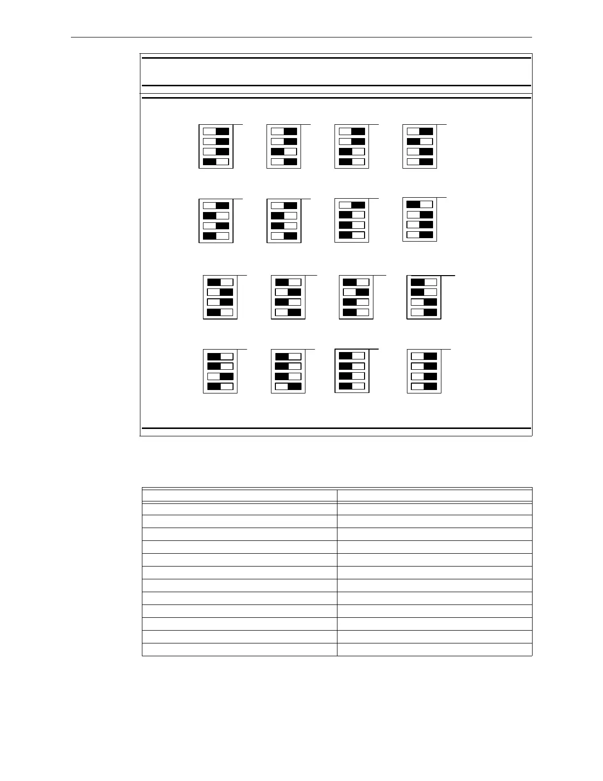
Figure 2.7.11.1 Binary Switches
Table 2.7.11.1 LCD-SLP Installation Wiring Terminals (Continued)
4
3
2
1
4
3
2
1
4
3
2
1
4
3
2
1
SW1 SW1 SW1 SW1
DISPLAY #1 DISPLAY #2 DISPLAY #3 DISPLAY #4
OFF OFF OFF OFF
OFF
THE PANEL MUST BE PROGRAMMED TO SET THE NUMBER OF DISPLAYS FOR SUPERVISION.
DISPLAY #5
4
3
2
1
SW1
4
3
2
1
SW1
DISPLAY #6
DISPLAY #7
4
3
2
1
SW1
OFFOFF
4
3
2
1
4
3
2
1
4
3
2
1
4
3
2
1
SW1 SW1 SW1 SW1
DISPLAY #9 DISPLAY #10 DISPLAY #11
DISPLAY #12
OFF
OFF OFF OFF
OFF
DISPLAY #13
4
3
2
1
SW1
4
3
2
1
SW1
DISPLAY #14 DISPLAY #0
4
3
2
1
SW1
OFF
OFF
UNSUPERVISED
4
3
2
1
SW1
DISPLAY #8
OFF
DISPLAY #15
4
3
2
1
SW1
OFF
Requirements LCD-SLP Specifications
Circuit Supervision: Supervised
Nominal Voltage, Frequency: + 24 VDC
Operating Standby Current: 0.030 A
Alarm Current: 0.065 A
Ground fault test impedance: Zero Ohms
Impedance values and ground faults are annunciated: GND Fault LED or LCD-SLP
Relative Humidity: 0 to 93%, non-condensing at 90° F (32° C)
Operating Temperature: 32° to 120° F (0° to 49° C)
Circuit Supervision: Supervised
Circuit Power-Limited: Class 2 Power-Limited
Maximum current amp-hour capacity: N/A
Type of suitable battery: N/A
Table 2.7.12.1 LCD-SLP Keypad Specifications

 Loading...


