30 S3 Series UL Listing Document — P/N LS10005-051GF-E:D3 3/09/2016
Installation Wiring Communication Circuits
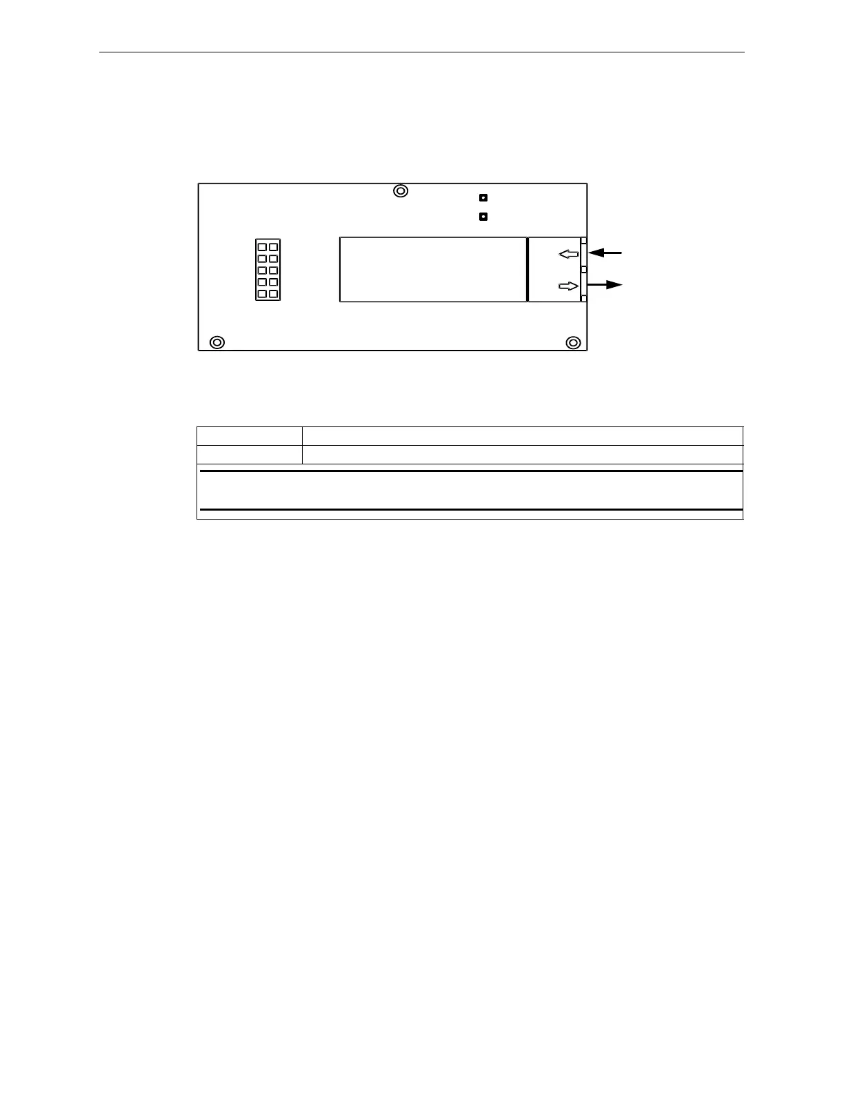
2.10.8 FSL-E3 Installation Wiring Diagram
The Fiber-Optic Single-Mode (FSL-E3) is an optional module that provides fiber connectivity to the network.
One FSL-E3 is used per a network channel to transmit/receive. Figure 2.10.8.1 lists the FSL-E3 (Fiber-Optic
Single-Mode) circuit board diagram. For system assembly and installation wiring terminal designations, refer
to the FML-E3/FSL-E3 Installation Instructions, P/N: LS10046-000GF-E. You can download this document
from the Gamewell-FCI Website (www.gamewell-fci.com).
Figure 2.10.8.1 FSL-E3 Circuit Board Diagram
2.10.9 FSL-E3 Installation Wiring Terminals
Table 2.10.9.1 lists the FSL-E3 terminal wiring designations.
2.10.10 DACT-E3 Communication Circuit
Use the DACT-E3 as the remote monitoring circuit for the S3 Series System. The DACT-E3 provides for sep-
arate transmissions for Alarm versus Trouble and Supervisory Events for the Remote Station Service. DACT
reporting of primary AC power failure maybe delayed. For information on the Programming Features, refer to
in Section 5.
For system assembly and installation wiring terminal designations and specifications, refer to the DACT-E3
Installation Instructions, P/N: 9000-0581. You can download this document from the Gamewell-FCI Website
(www.gamewell-fci.com).
J1
LED1
LED2
RX
TX
U6
FIBER IN
FIBER OUT
Designation Description
J1 Plugs on to J5 (Port 1) or J6 (Port 2) of the RPT-E3-UTP.
NOTE: Use LC connector fiber-optic cable, single mode, up to 1310 nm (optimized for 9/125 µ).
Signal loss up to 30 dB maximum between nodes.
Table 2.10.9.1 FSL-E3 Installation Wiring Terminals

 Loading...


