10 S3 Series UL Listing Document — P/N LS10005-051GF-E:D3 3/09/2016
Section 2: Installation Wiring
This product is intended to be installed in accordance with local, regional and National standards. The S3
Series System (Small Addressable Fire Alarm Control Panel) comprises the following modules.
2.1 Main Supply Circuit
The FLPS-7 is the main supply circuit for the S3 Series System.
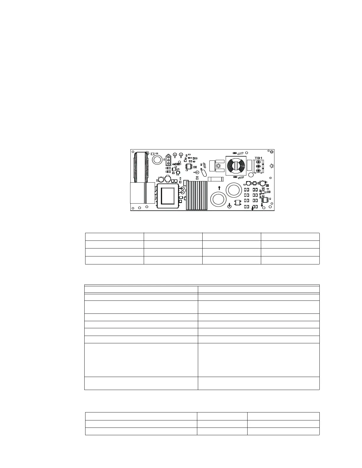
2.1.1 FLPS-7 Main Supply Installation Wiring Diagram
Figure 2.1.1.1 illustrates the FLPS-7 main supply circuit board diagram.
Figure 2.1.1.1 FLPS-7 Main Supply Circuit Board
2.1.2 FLPS-7 Installation Wiring Terminals
Table 2.1.2.1 lists the FLPS-7 power supply installation wiring terminals.
2.1.3 FLPS-7 Main Supply Circuit Specifications
The FLPS-7 is the main supply circuit for the S3 Series panel. Table 2.1.3.1 lists the FLPS-7 specifications.
2.1.4 Cabinet Enclosures for the FLPS-7
Table 2.1.4.1 lists the cabinet enclosure you can use to install the SLP main board.
Required Modules Optional Modules
• SLP-E3 (Smart Loop Panel-Main Board) • LCD-E3, LCD-7100/RAN-7100
(Remote Display Modules)
• SLC-PM or SLC95-PM (Signaling Loop Circuit
Driver
• DACT-E3
(Digital Alarm Communicator Transmitter)
Module for System Sensor or Apollo Loop
Devices)
• ASM-16/ANU-48 (Switch LED Modules)
•LCD-SLP
(Lead Crystal Display-Smart Loop Panel)
• RPT-E3-UTP (Repeater Module)
– FML-E3 (Fiber-Optic Multi-Mode)
– FSL-E3 (Fiber-Optic Single-Mode)
• FLPS-7 (7 Amp Power Supply)
L1 GROUND L2
JP6
JP5
FLPS-7
J1
Designation Description Designation Description
L1 AC Power - Hot J1 Power output connector
EARTH Earth Ground JP5 Factory set to 120 VAC
L2 AC Power - Neutral JP6 Factory set to 120 VAC
Table 2.1.2.1 FLPS-7 Installation Wiring Terminals
Requirements FLPS-7 Specifications
Circuit Supervision: Supervised
Nominal Voltage, Frequency: 120 V AC, 60 Hz, Max. 2.75 Amps
240 V AC, 50/60 Hz, Max. 1.4 Amps
Max.current or power supply to be used: FLPS-7, 7 amperes power supply, 7 A 24 VDC
Terminal for the connection of a grounded conductor: See Figure 2.1.1.1.
Operating Temperature: 32° to 120° F (0° to 49° C)
Operating Humidity: 0 to 93%, non-condensing at 90° F (30° C)
The maximum time during which the standby
operating source maintains the minimum operating
voltage (85 percent of rated voltage). This is required
for releasing devices under continuous load that can’t
maintain 85 percent of the rated operating voltage to
the releasing devices for 60 seconds after energizing.
N/A
Type of device (automatic, manual, waterflow,
sprinkler supervisory, watchman supervisory, etc.).
Refer to Section 1.3 (Product Models Nomenclature),
Table 1.3.1 (Product Models Nomenclature).
Table 2.1.3.1 FLPS-7 Main Supply Circuit Specifications
Cabinet Part Numbers Dimensions
SLP-BB cabinet (also called the B-Slim cabinet) SLP-BB 14.1/2” W x 20 1/8” H x 4 1/2” D
S3 Series, Cabinet B-Size S3BB-BB/RB 19.38” W x 19.38” H x 4.50” D
Table 2.1.4.1 FLPS-7 Main Board Cabinet

 Loading...


